Solar photovoltaic (PV) arrays are the primary energy-generating components of a solar power system. They capture sunlight and convert it into direct current (DC) electricity, which is then supplied to the inverter for conversion into alternating current (AC) for residential, commercial, industrial, and utility-scale applications. The efficiency, reliability, and overall performance of a renewable solar system depend heavily on the proper operation of the PV array. Even minor issues such as shading, dirt accumulation, loose connectors, damaged modules, or wiring faults can significantly reduce solar electricity generation and lower the return on investment.
A solar PV array consists of multiple interconnected modules arranged in series and parallel configurations to achieve the desired voltage and current output. Since these arrays are continuously exposed to harsh environmental conditions—including high temperatures, ultraviolet (UV) radiation, rain, dust, wind, humidity, bird droppings, and mechanical stress—they are susceptible to performance degradation and physical damage over time. Common faults include cracked modules, hot spots, Potential Induced Degradation (PID), connector failures, insulation faults, ground faults, broken bypass diodes, shading losses, and cable damage.
Routine inspection and systematic troubleshooting of solar PV arrays are essential to identify performance issues before they lead to significant energy losses or equipment failures. Effective troubleshooting involves visual inspections, electrical measurements, thermal imaging, insulation resistance testing, irradiance measurement, string performance comparison, and proper documentation. By following a structured troubleshooting process, technicians can accurately identify faults, restore system performance, improve solar electricity production, and extend the lifespan of the entire solar installation.
Troubleshooting solar PV arrays is a core competency for solar installers, commissioning engineers, EPC contractors, and Operations & Maintenance (O&M) professionals.
This comprehensive guide explains common PV array faults, troubleshooting procedures, testing methods, required tools, documentation practices, safety precautions, and industry best practices.
What Is a Solar PV Array?
A solar PV array is a group of interconnected solar modules that work together to generate DC electricity from sunlight.
A typical PV array includes:
- Solar PV modules
- Mounting structures
- DC cables
- MC4 connectors
- Junction boxes
- Combiner boxes
- String fuses
- Surge Protection Devices (SPDs)
- Grounding system
The PV array is the primary source of solar electricity generation.
Why Is Solar PV Array Troubleshooting Important?
Routine troubleshooting helps to:
- Maximize energy generation
- Improve module efficiency
- Detect damaged components early
- Reduce system downtime
- Improve renewable solar system reliability
- Extend equipment lifespan
- Lower maintenance costs
- Improve safety
Early detection of faults minimizes production losses.
Common Solar PV Array Problems
Technicians commonly encounter:
- Low power generation
- Cracked PV modules
- Broken glass
- Delamination
- Hot spots
- Potential Induced Degradation (PID)
- Discoloration
- Burn marks
- Loose MC4 connectors
- Damaged DC cables
- Open circuits
- Short circuits
- Ground faults
- Reverse polarity
- Shading losses
- Soiling (dust, dirt, bird droppings)
- Water ingress
- Corroded connectors
- Failed bypass diodes
- Module mismatch
Each fault requires systematic diagnosis.
Common Causes of PV Array Faults
Solar array problems may result from:
- Dust accumulation
- Tree shading
- Nearby buildings
- Bird nests
- Improper installation
- Loose electrical connections
- Aging modules
- UV degradation
- Thermal cycling
- Wind damage
- Hail impact
- Rodent damage
- Moisture ingress
- Corrosion
- Manufacturing defects
Understanding the cause helps prevent recurring issues.
Tools Required
Technicians commonly use:
- Digital multimeter
- Clamp meter
- Insulation resistance tester (Megger)
- Earth resistance tester
- Solar irradiance meter
- Infrared thermal camera
- I-V curve tracer
- Continuity tester
- DC voltage tester
- Torque wrench
- Personal Protective Equipment (PPE)
Only calibrated instruments should be used.
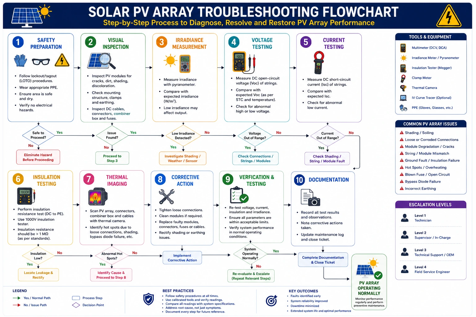
Step-by-Step Solar PV Array Troubleshooting Procedure
Step 1 – Ensure Safety
Before inspection:
- Follow Lockout/Tagout (LOTO) procedures where applicable.
- Isolate circuits if required.
- Wear appropriate PPE.
- Verify safe weather conditions before rooftop work.
Safety should always come first.
Step 2 – Review System Documentation
Check:
- Single-line diagram (SLD)
- Array layout drawings
- String configuration
- Commissioning reports
- Previous maintenance records
- Module specifications
System documentation simplifies troubleshooting.
Step 3 – Perform a Visual Inspection
Inspect for:
- Broken modules
- Cracked glass
- Burn marks
- Delamination
- Loose mounting hardware
- Corroded connectors
- Damaged cables
- Loose MC4 connectors
- Bird nests
- Dirt accumulation
- Water ingress
Many faults are visible without electrical testing.
Step 4 – Inspect for Shading
Check for:
- Tree growth
- Nearby structures
- Utility poles
- Antennas
- Water tanks
- Seasonal shading
Even partial shading can significantly reduce solar electricity generation.
Step 5 – Measure Solar Irradiance
Using a solar irradiance meter:
- Measure available sunlight during testing.
Electrical measurements should be interpreted relative to irradiance conditions.
Step 6 – Measure String Open Circuit Voltage (Voc)
Measure:
- Individual string voltage
- Array voltage
Compare measured values with design calculations and manufacturer specifications. Abnormal voltage may indicate open circuits or damaged modules.
Step 7 – Measure Short Circuit Current (Isc)
Measure:
- Individual string current
- Array current
Compare current values between strings. Lower current often indicates shading, damaged modules, or poor electrical connections.
Step 8 – Perform Continuity Testing
Verify:
- Cable continuity
- Connector integrity
- Proper string connections
Open circuits require immediate investigation.
Step 9 – Perform Insulation Resistance Testing
Use an insulation resistance tester to evaluate:
- Cable insulation
- Module insulation
- Ground leakage
Low insulation resistance may indicate damaged wiring or moisture ingress.
Step 10 – Conduct Thermal Imaging
Using an infrared thermal camera:
Inspect for:
- Hot spots
- Failed bypass diodes
- Loose electrical connections
- Overheated connectors
- Damaged cells
Thermal imaging detects hidden defects that may not be visible.
Step 11 – Inspect Mounting Structure
Verify:
- Structural integrity
- Loose bolts
- Corrosion
- Module clamps
- Wind damage
Mechanical issues can affect electrical performance.
Step 12 – Compare String Performance
Review monitoring data to compare:
- String voltage
- String current
- Energy generation
- Daily performance
One underperforming string often indicates localized faults.
Step 13 – Implement Corrective Actions
Depending on the diagnosis:
- Clean PV modules
- Tighten connectors
- Replace damaged cables
- Replace faulty modules
- Replace bypass diodes (where serviceable)
- Remove shading obstacles where possible
- Correct polarity errors
- Repair grounding faults
Only approved corrective actions should be performed.
Step 14 – Verify System Performance
After repairs:
Confirm:
- Stable inverter operation
- Correct string voltage
- Correct string current
- Normal energy generation
- Balanced array performance
The PV array should operate within expected performance limits.
Step 15 – Document Findings
Record:
- Visual observations
- Irradiance
- Voltage measurements
- Current measurements
- Thermal images
- Corrective actions
- Final performance
- Technician details
Proper documentation supports preventive maintenance.
Conclusion
Solar PV arrays are the foundation of every solar power system, and their performance directly determines the amount of solar electricity generated. Because PV arrays operate continuously under varying environmental conditions, they are vulnerable to physical damage, electrical faults, environmental contamination, and gradual performance degradation. A systematic troubleshooting process, including visual inspections, irradiance measurements, electrical testing, thermal imaging, insulation resistance testing, string performance analysis, and detailed documentation, enables technicians to identify faults accurately, restore optimal energy production, and prevent minor issues from developing into major system failures.
Troubleshooting solar PV arrays is an essential competency for solar installers, EPC contractors, commissioning engineers, and operations and maintenance professionals. Furthermore, adhering to technical recommendations and safety practices promoted by the Ministry of New and Renewable Energy, together with manufacturer guidelines and local electrical standards, ensures that PV array inspections and corrective actions are carried out safely, accurately, and in compliance with industry requirements.
By performing routine inspections, cleaning modules regularly, maintaining secure electrical connections, using calibrated testing instruments, implementing timely corrective actions, and maintaining comprehensive maintenance records, solar professionals can optimize solar panel system cost, improve renewable solar system reliability, maximize solar electricity generation, reduce the cost of solar per kWh installed, lower the solar installation cost per kWh, support solar energy for home use, and ensure the long-term success of residential, commercial, industrial, and utility-scale solar energy projects.
FAQs
Q1. What are the most common faults in solar PV arrays?
Ans: Common faults include cracked modules, hot spots, shading losses, loose MC4 connectors, damaged DC cables, insulation failures, ground faults, Potential Induced Degradation (PID), failed bypass diodes, and dirt accumulation that reduces energy generation.
Q2. Why is thermal imaging important when troubleshooting solar PV arrays?
Ans: Infrared thermal imaging helps detect hidden defects such as hot spots, loose electrical connections, overheating connectors, damaged cells, and failed bypass diodes that may not be visible during a standard visual inspection.
Q3. How can technicians identify an underperforming solar string?
Ans: Technicians compare string voltage, short-circuit current (Isc), operating current, energy production data, and monitoring system records. Significant differences between strings usually indicate shading, damaged modules, connector issues, or wiring faults.
Q4. What causes reduced power generation in a solar PV array?
Ans: Reduced generation may result from dust, bird droppings, shading, damaged modules, loose electrical connections, insulation faults, degraded modules, high operating temperatures, incorrect string configuration, or inverter-related issues.
Q5. How often should solar PV arrays be inspected?
Ans: Visual inspections should be carried out regularly as part of preventive maintenance, while electrical testing, thermal imaging, insulation resistance measurements, and performance verification should be performed according to manufacturer recommendations, project maintenance schedules, and applicable industry standards.
Maintenance Of Solar Power Plant in India: Everything You Need to know
Proper maintenance is key to maximizing the efficiency and lifespan of solar power plants in India. Learn essential tips, best practices, and common maintenance tasks.
Stop Losing Power: The Ultimate Guide to Solar DC & AC Cable Sizing for Max Efficiency
DC and AC cabling are the lifelines of any Solar PV Rooftop System. Learn how proper cable selection, connection design, and installation can help achieve optimum power output and long-term safety.
Steps Required for Conducting a Site Assessment Prior to Solar Installation
A solar site assessment helps installers evaluate location, shading, structure, and energy requirements before installation. This guide explains the essential steps for accurate solar system planning.
How to Check Solar PV Module Performance
A complete guide to testing solar PV module performance, including voltage and current measurements, power output analysis, and performance verification techniques.
Battery Inspection in Solar PV Systems Guide
A complete guide to battery inspection in solar PV systems, helping identify performance issues, safety concerns, and maintenance requirements.
Data Acquisition System Calibration in Solar PV Plants
A complete guide to solar PV data acquisition system calibration, ensuring accurate monitoring, reliable data collection, and effective performance analysis.
How to Check Materials Received on Site for Solar PV Projects: Complete Inspection Checklist
Ensuring the quality of materials received at site is critical for successful solar PV installation. This guide provides a detailed inspection checklist to verify solar components before installation.
Solar Panel Specifications Explained: How to Read Datasheets & Choose the Right PV Module
Choosing the right solar panel requires a clear understanding of technical specifications. This guide explains how to read solar panel datasheets, interpret key parameters, and select the best PV module for your project.