In every solar photovoltaic (PV) installation, cables serve as the pathways that transport electrical energy between solar modules, combiner boxes, inverters, batteries, disconnects, and the utility grid. Even when high-quality solar panels and advanced inverters are used, the entire system can underperform or become unsafe if cable connections are faulty. This is why continuity testing is a critical part of solar PV installation, commissioning, troubleshooting, and maintenance.
A continuity test verifies that an electrical conductor provides a complete and uninterrupted path for current flow. It helps identify broken conductors, loose connections, improper terminations, damaged cables, and wiring errors before the system is energized. Performing continuity tests is essential for ensuring safety, preventing equipment damage, improving renewable solar system performance, and reducing costly maintenance issues.
Continuity testing is typically carried out during cable installation, before system commissioning, after repairs, and as part of periodic maintenance inspections. Proper testing helps installers confirm that all wiring has been installed according to project drawings and design specifications.
Electrical verification procedures such as continuity testing are fundamental requirements for safe solar electricity generation and successful renewable energy technology implementation.
This comprehensive guide explains the purpose of continuity testing, testing methods, required tools, step-by-step procedures, safety precautions, documentation requirements, and industry best practices.
What is a Continuity Test?
A continuity test is an electrical verification procedure used to determine whether a conductor provides a complete electrical path between two points.
The test confirms that:
- The conductor is not broken
- Connections are properly completed
- Electrical pathways are continuous
A successful continuity test indicates that electricity can flow through the conductor as intended.
Why Continuity Testing is Important in Solar PV Systems
Solar installations contain extensive cable networks connecting various components.
Continuity testing helps:
- Verify cable integrity
- Detect installation errors
- Identify damaged conductors
- Prevent equipment damage
- Improve system safety
- Reduce troubleshooting time
Without continuity testing, hidden wiring faults may remain undetected until system operation begins.
Objectives of Continuity Testing
The primary objectives include:
Verifying Electrical Connections
Ensuring conductors are properly connected.
Identifying Open Circuits
Detecting broken or disconnected conductors.
Confirming Correct Installation
Verifying wiring matches design drawings.
Supporting Safe Commissioning
Ensuring the system is safe before energization.
Reducing Future Maintenance Issues
Identifying problems before they become operational failures.
Where Continuity Testing is Performed in Solar PV Systems
Continuity testing may be required for several system components.
1. Solar Module String Cables
Verifies continuity of conductors connecting PV modules.
2. DC Array Cables
Checks wiring between arrays and combiner boxes.
3. Combiner Box Connections
Ensures proper cable connections within combiner boxes.
4. Inverter Cables
Verifies continuity between DC inputs, AC outputs, and associated equipment.
5. Battery Interconnection Cables
Confirms electrical continuity in battery banks.
6. Grounding Conductors
Ensures proper grounding system continuity.
7. AC Distribution Cables
Checks continuity between inverters and distribution panels.
Importance of Continuity Testing During Commissioning
Commissioning activities require verification that all electrical pathways are complete and functional.
Continuity testing helps:
- Prevent startup failures
- Reduce commissioning delays
- Improve installation quality
- Ensure compliance with project specifications
Tools Required for Continuity Testing
Several tools may be used depending on project requirements.
1. Digital Multimeter
The most commonly used tool for continuity testing.
Features include:
- Continuity mode
- Resistance measurement
- Audible continuity indication
2. Continuity Tester
A dedicated instrument designed specifically for continuity verification.
3. Clamp Meter
May assist with related electrical testing activities.
4. Test Leads and Probes
Used to connect testing instruments to conductors.
5. Project Drawings and Cable Schedules
Used to verify cable identification and routing.
Understanding Continuity Test Results
During testing:
- Continuity Present
Indicates:
- Complete electrical path
- Proper conductor installation
Most meters emit an audible tone.
No Continuity
Indicates:
- Broken conductor
- Loose connection
- Wiring fault
- Open circuit
Further investigation is required.
Pre-Test Inspection Requirements
Before conducting continuity tests:
- Verify System Isolation
Ensure circuits are de-energized.
Review Project Documentation
Check:
- Wiring diagrams
- Cable schedules
- Single-line diagrams
Inspect Cables Visually
Look for:
- Physical damage
- Loose connections
- Improper terminations
- Confirm Equipment Safety
Ensure safe access to testing points.

Step-by-Step Procedure for Performing Continuity Tests
Step 1 – De-Energize the Circuit
- Continuity testing must only be performed on de-energized circuits.
- Verify absence of voltage before proceeding.
Step 2 – Isolate the Cable
- Disconnect the cable from equipment if required by testing procedures.
- This prevents false readings.
Step 3 – Set the Multimeter to Continuity Mode
Select the continuity function on the digital multimeter.
Many meters provide:
- Audible indication
- Visual indication
Step 4 – Verify Meter Operation
Touch the test probes together.
A proper meter should:
- Produce a tone
- Display very low resistance
Step 5 – Connect Test Probes to Both Ends of the Cable
Place one probe at each end of the conductor. Ensure good electrical contact.
Step 6 – Observe the Reading
Interpret results:
- Continuous Path
- Audible tone present
- Low resistance reading
- Open Circuit
- No tone
- High or infinite resistance
Step 7 – Record Results
Document:
- Cable identification
- Test results
- Observations
- Corrective actions if required
Continuity Testing for Grounding Conductors
Grounding systems are critical for solar PV safety.
Verify continuity between:
- Modules
- Mounting structures
- Grounding electrodes
- Electrical equipment
Proper grounding continuity improves fault protection.
Continuity Testing for Battery Systems
Battery installations require verification of:
- Interconnection cables
- Battery bank conductors
- Grounding conductors
This ensures safe battery operation.
Continuity Testing for AC Circuits
Verify continuity in:
- Distribution wiring
- Disconnect switches
- Utility interconnection conductors
This helps identify wiring issues before energization.
Common Causes of Continuity Test Failures
Broken Conductors
May result from:
- Physical damage
- Improper handling
- Installation errors
Loose Connections
Poor terminations can interrupt electrical continuity.
Incorrect Wiring
Wiring errors may create open circuits or incorrect connections.
Corrosion
Corrosion can increase resistance or interrupt electrical pathways.
Connector Failures
Damaged connectors may prevent proper continuity.
Troubleshooting Failed Continuity Tests
If continuity is not present:
Inspect Cable Ends
- Verify proper terminations.
Check Connectors
- Look for damaged or loose connections.
Inspect Cable Routing
- Identify possible physical damage.
Compare with Drawings
- Confirm correct wiring configuration.
Retest After Corrections
- Verify successful repairs.
Conclusion
Performing continuity tests for cables is an essential step in the installation, commissioning, troubleshooting, and maintenance of solar PV systems. Continuity testing verifies the integrity of electrical pathways, identifies wiring defects, confirms proper installation practices, and ensures that conductors can safely carry current throughout the solar power system.
Continuity verification is a fundamental electrical testing procedure that supports safe solar electricity generation and effective renewable energy technology implementation. Furthermore, adhering to recommendations and quality standards promoted by the Ministry of New and Renewable Energy helps ensure reliable and compliant solar PV installations.
By following approved testing procedures, using calibrated instruments, documenting results accurately, and correcting identified issues promptly, solar installers, EPC contractors, and maintenance professionals can optimize solar panel system cost, improve renewable solar system reliability, reduce operational risks, and ensure the long-term success of residential, commercial, industrial, and utility-scale solar PV projects.
FAQs
Q1. What is a continuity test in a solar PV system?
Ans: A continuity test verifies that a conductor provides a complete electrical path and is free from breaks, open circuits, or connection faults.
Q2. Why is continuity testing important before commissioning?
Ans: It helps identify wiring problems, installation errors, and damaged conductors before the system is energized.
Q3. Which tool is most commonly used for continuity testing?
Ans: A digital multimeter with a continuity function is the most commonly used testing instrument.
Q4. Can continuity testing be performed on energized circuits?
Ans: No. Continuity testing must only be performed on de-energized and isolated circuits to prevent injury and equipment damage.
Q5. What should be done if continuity is not detected?
Ans: Inspect cable terminations, connectors, cable routing, and wiring configurations, then perform repairs and retest the circuit.

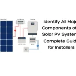
How to Check Materials Received on Site for Solar PV Projects: Complete Inspection Checklist
Ensuring the quality of materials received at site is critical for successful solar PV installation. This guide provides a detailed inspection checklist to verify solar components before installation.
How to Prepare a Bill of Material (BOM) for Solar PV Systems: Step-by-Step Installer Guide
Learn how to prepare a detailed Bill of Material (BOM) for solar PV systems using design documents like SLDs and layouts. This step-by-step guide helps installers ensure accurate material planning, reduce errors, and improve project execution.
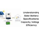
Understanding Solar Battery Specifications: Capacity, Voltage & Efficiency Explained
Solar batteries are essential for energy storage and backup in PV systems. This guide explains key specifications like capacity, voltage, efficiency, and depth of discharge to help you choose the right battery.

India’s Solar Capacity Growth Slows Down in Q1 2023
India’s solar capacity growth slowed in Q1 2023. Explore the factors behind the slowdown and its impact on the country’s renewable energy progress.

Solar System for FMCG Industry: Cost, Benefits, Installation & ROI in India
A complete guide on solar systems for the FMCG industry in India covering installation cost, benefits, ROI, system sizing, and the installation process.

Get a Customized Industrial Solar Quote for Your Manufacturing Unit
Request a customized industrial solar quote in India. Know pricing, savings, payback & EPC scope for your factory solar project.
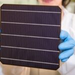
Perovskite: Future of Solar Cells
Discover how solar batteries store excess energy, maximize your solar system’s efficiency, and provide reliable power during outages. Learn about the types, benefits, lifespan, and maintenance tips to make the most of your solar investment.

500 kW Solar Power Plant Cost in UP 2025 | Latest Price, Subsidy & ROI
Thinking of setting up a 500 kW solar power plant in Uttar Pradesh? Discover the 2025 cost estimate, available subsidies, and expected ROI. Learn how commercial and industrial projects in UP can reduce energy expenses and achieve long-term savings with solar energy.