Solar photovoltaic (PV) inverters are the heart of a solar power system, converting the direct current (DC) produced by solar modules into usable alternating current (AC) for homes, businesses, industries, or utility grids. For the inverter to operate safely and efficiently, all incoming and outgoing electrical connections must remain secure, correctly terminated, properly insulated, and free from physical or electrical damage. Even a minor defect in a wire connection can lead to voltage drops, overheating, arc faults, inverter shutdowns, reduced energy generation, equipment failure, and serious safety hazards.
The inverter is connected to multiple electrical circuits, including PV strings, DC combiner boxes, battery banks (in hybrid or off-grid systems), AC distribution panels, grounding systems, communication cables, and monitoring equipment. Because these connections are continuously exposed to thermal cycling, vibration, moisture, dust, UV radiation, and high operating currents, they can gradually deteriorate over time. Loose terminals, damaged insulation, corroded conductors, improperly crimped lugs, overheated connectors, and mechanical stress are among the most common causes of inverter connection failures.
Routine inspection of inverter wire connections is therefore a critical preventive maintenance activity. By systematically checking the condition of cables, connectors, terminals, and grounding conductors, technicians can identify problems early, restore reliable operation, and prevent costly equipment damage or downtime.
Inspecting inverter wire connections and identifying damaged conductors are essential maintenance responsibilities for solar installers, commissioning engineers, EPC contractors, and operations and maintenance (O&M) professionals.
This comprehensive guide explains the importance of inverter wiring inspections, common causes of wire damage, testing procedures, required tools, documentation practices, safety precautions, and industry best practices.
Why Are Inverter Wire Connections Important?
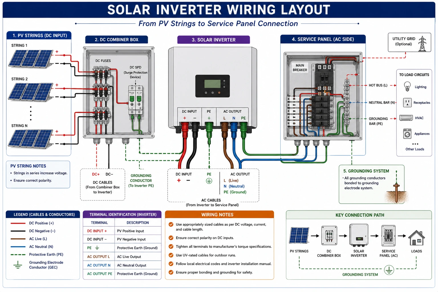
Inverter wire connections are responsible for:
- Carrying DC power from the PV array to the inverter.
- Delivering AC power to the electrical distribution system.
- Connecting battery banks in hybrid and off-grid systems.
- Providing grounding and bonding protection.
- Supporting monitoring and communication systems.
Faulty connections can reduce solar electricity generation and compromise system safety.
Why Should Inverter Connections Be Inspected Regularly?
Routine inspections help to:
- Prevent inverter shutdowns
- Detect overheating early
- Reduce voltage losses
- Improve renewable solar system efficiency
- Increase solar electricity production
- Reduce fire risks
- Extend equipment lifespan
- Lower maintenance costs
Preventive maintenance improves long-term system reliability.
Types of Inverter Wire Connections
Technicians may inspect:
- PV string DC input cables
- DC combiner box output cables
- Battery cables
- AC output cables
- Neutral conductors
- Grounding conductors
- Communication cables
- Monitoring system wiring
- Control wiring
- Remote shutdown wiring
Each connection must remain secure and undamaged.
Common Causes of Wire Connection Damage
Inverter wiring may be damaged due to:
- Loose terminals
- Improper crimping
- Overheating
- Excessive current
- Vibration
- Thermal expansion and contraction
- Corrosion
- Moisture ingress
- UV exposure
- Rodent damage
- Mechanical stress
- Improper cable routing
- Aging insulation
Regular inspections help identify these problems before they become critical.
Signs of Damaged Wire Connections
Technicians should inspect for:
- Burn marks
- Discoloration
- Melted insulation
- Cracked insulation
- Loose terminals
- Corroded conductors
- Exposed copper
- Broken strands
- Damaged lugs
- Overheated connectors
- Unusual odor
- Arc marks
Any abnormal condition should be investigated immediately.
Tools Required
Technicians commonly use:
- Digital multimeter
- Clamp meter
- Insulation resistance tester (Megger)
- Continuity tester
- Infrared thermal camera
- Torque wrench
- Screwdriver set
- Inspection flashlight
- Personal Protective Equipment (PPE)
Only calibrated instruments should be used.
Step-by-Step Inspection Procedure
Step 1 – Ensure Safety
Before beginning work:
- Follow Lockout/Tagout (LOTO) procedures where applicable.
- Isolate DC and AC circuits if required.
- Wear appropriate PPE.
- Verify the work area is safe.
Safety should always be the first priority.
Step 2 – Review System Documentation
Review:
- Single-line diagram (SLD)
- Wiring diagrams
- Cable schedule
- Previous maintenance records
- Manufacturer instructions
Documentation helps verify correct wiring arrangements.
Step 3 – Perform Visual Inspection
Inspect all visible inverter connections for:
- Loose terminals
- Corrosion
- Damaged insulation
- Burn marks
- Cracked connectors
- Discoloration
- Moisture ingress
- Dust accumulation
Correct any visible defects immediately.
Step 4 – Inspect DC Input Connections
Check:
- String cable terminations
- MC4 connectors
- DC terminals
- Combiner box connections
- Polarity markings
Verify all connections are secure and properly identified.
Step 5 – Inspect AC Output Connections
Inspect:
- AC conductors
- Neutral conductors
- Breaker connections
- Service panel terminations
- Cable lugs
Loose AC connections can lead to overheating and inverter trips.
Step 6 – Inspect Grounding Connections
Verify:
- Grounding conductor continuity
- Secure grounding terminals
- Proper bonding
- Corrosion-free connections
Grounding is critical for electrical safety.
Step 7 – Verify Tightness of Connections
Using a calibrated torque wrench:
- Tighten all accessible terminals according to manufacturer specifications.
Overtightening should be avoided.
Step 8 – Perform Continuity Testing
Using a multimeter or continuity tester:
- Verify conductor continuity.
Open circuits indicate damaged conductors or failed connections.
Step 9 – Measure Insulation Resistance
Use an insulation resistance tester to verify insulation integrity.
Low insulation resistance may indicate:
- Moisture ingress
- Damaged insulation
- Contamination
- Cable deterioration
Further investigation is required if readings are outside acceptable limits.
Step 10 – Perform Thermal Inspection
Use an infrared thermal camera to identify:
- Hot terminals
- Loose connections
- Overheated conductors
- High-resistance joints
Thermal anomalies require immediate corrective action.
Step 11 – Replace Damaged Components
Replace:
- Damaged cables
- Corroded terminals
- Defective connectors
- Burnt lugs
- Loose cable glands
Use only approved replacement components.
Step 12 – Verify Normal Operation
After repairs:
Verify:
- Stable inverter startup
- Correct voltage
- Normal current flow
- Reliable communication
- Proper energy generation
Ensure the inverter operates normally after maintenance.
Step 13 – Prepare the Inspection Report
Document:
- Cable identification
- Inspection findings
- Electrical measurements
- Thermal inspection results
- Corrective actions
- Technician details
Accurate records support preventive maintenance.
Common Wire Connection Faults and Corrective Actions
Fault | Corrective Action |
Loose terminal | Tighten according to torque specifications |
Burnt conductor | Replace affected cable |
Corroded terminal | Clean or replace terminal |
Damaged insulation | Replace cable |
Loose lug | Re-terminate or replace |
Overheated connector | Replace connector and inspect load conditions |
Conclusion
Checking inverter wire connections and identifying damaged conductors are essential preventive maintenance activities that directly affect the safety, reliability, and performance of solar PV systems. Since the inverter serves as the central power conversion unit, any loose connection, damaged cable, corroded terminal, or deteriorated insulation can reduce efficiency, interrupt solar electricity generation, create electrical hazards, and shorten equipment lifespan. By conducting systematic inspections, verifying terminal tightness, performing continuity and insulation resistance testing, carrying out thermal inspections, and replacing damaged components promptly, technicians can significantly improve overall system reliability and reduce unplanned downtime.
Inspecting inverter wire connections is a core maintenance responsibility for solar installers, EPC contractors, commissioning engineers, and operations and maintenance professionals. Furthermore, following technical recommendations and safety practices promoted by the Ministry of New and Renewable Energy, together with manufacturer guidelines and local electrical standards, ensures that inspections are performed safely, accurately, and in compliance with industry requirements.
By implementing regular inspection schedules, maintaining detailed maintenance records, using calibrated testing instruments, replacing damaged wiring without delay, and adhering to preventive maintenance best practices, solar professionals can optimize solar panel system cost, enhance renewable solar system reliability, maximize solar electricity generation, reduce the cost of solar per kWh installed, and ensure the long-term success of residential, commercial, industrial, and utility-scale solar energy projects.
FAQs
Q1. Why should inverter wire connections be inspected regularly?
Ans: Inverter wire connections are exposed to heat, vibration, electrical loading, and environmental conditions. Routine inspections help identify loose terminals, overheating, corrosion, and insulation damage before they cause inverter failures or safety hazards.
Q2. What are the common signs of damaged inverter wiring?
Ans: Common signs include burn marks, melted insulation, discoloration, loose terminals, exposed conductors, corrosion, unusual odors, overheating, and repeated inverter fault alarms.
Q3. How can technicians detect overheating in inverter connections?
Ans: Infrared thermal cameras are commonly used to identify hot spots, loose terminals, and high-resistance electrical joints that may not be visible during a normal inspection.
Q4. Why is torque verification important for inverter terminals?
Ans: Incorrect tightening can lead to loose connections, overheating, electrical arcing, and equipment damage. Using the manufacturer’s recommended torque values ensures secure and reliable connections.
Q5. What should be done if damaged wires are found during inspection?
Ans: Damaged conductors, connectors, or terminals should be replaced immediately with approved components after identifying and correcting the root cause of the damage before returning the inverter to service.

Solar for Warehouses and Malls: Cost, Benefits, Installation & ROI in India
A complete guide on solar for warehouses and malls in India covering installation cost, benefits, ROI, system sizing, and installation process.
Battery Troubleshooting in Solar PV Systems Guide
A complete guide to battery troubleshooting in solar PV systems, including fault diagnosis, performance testing, common battery issues, and effective corrective measures.

Solar Savings Made Simple: Know Your Cost Cuts in 2025
Maximize your solar savings in 2025. Learn how solar energy reduces electricity costs for homes and businesses.
Inverter-Wise Solar Generation for C&I Plants
Discover how inverter-wise solar generation monitoring helps commercial and industrial (C&I) solar plants identify underperforming inverters, detect faults early, compare performance, and improve overall energy generation.
Solar ROI vs Payback Period Explained for Commercial & Industrial Projects
Compare payback period and ROI for solar systems. Discover how businesses should evaluate solar investments effectively.

Solar PV Cable Selection Guide: Type, Color & Gauge
A complete guide to selecting solar PV cable type, color, and gauge for safe, efficient, and reliable solar system installation.
Installation of DC Combiner Box with Disconnect Protection: Step-by-Step Guide
A DC combiner box is an important protection component in solar PV systems. This guide explains its installation, disconnect protection, wiring, and safety requirements.
Cable Continuity Testing in Solar Installations Guide
A complete guide to cable termination in solar installations, including tools, step-by-step methods, and best practices for safe connections.