In solar photovoltaic (PV) systems, cables play a vital role in transmitting solar electricity safely and efficiently between different components such as solar modules, inverters, batteries, combiner boxes, and utility connections. Proper cable installation is essential for ensuring system reliability, minimizing energy losses, and maintaining long-term safety.
Incorrect cable installation can lead to voltage drop, overheating, insulation failure, short circuits, fire hazards, and increased solar installation charges. Therefore, installers and EPC professionals must follow proper cable installation procedures and safety standards during solar PV system deployment.
Correct electrical wiring and cable management are fundamental parts of renewable solar projects and solar energy for home use.
This blog provides a complete step-by-step guide to installing cables for solar modules, inverters, batteries, and other solar PV components, including cable types, routing methods, safety precautions, testing procedures, and best practices.
Importance of Proper Cable Installation in Solar PV Systems
Proper cable installation helps:
- Improve solar electricity generation efficiency
- Reduce voltage drop
- Prevent electrical faults
- Improve safety and reliability
- Simplify maintenance and troubleshooting
- Optimize solar panel system cost
Improper installation can increase:
- Power losses
- Maintenance costs
- Solar installation cost per kWh
Major Components Connected Through Cables
1. Solar Modules
- Generate DC electricity.
2. DC Combiner Box
- Combines solar panel strings.
3. Solar Inverter
- Converts DC power into AC electricity.
4. Battery Bank
- Stores electrical energy in off-grid and hybrid systems.
5. AC Combiner Box and Distribution Panel
- Manage AC power distribution.
6. Utility Grid Connection
- Exports or imports electricity.
Types of Cables Used in Solar PV Systems
1. DC Solar Cables
Used between:
- Solar modules
- Combiner boxes
- Inverters
Features:
- UV resistant
- Heat resistant
- Double insulated
2. AC Power Cables
Used between:
- Inverter output
- AC distribution systems
- Utility grid
3. Battery Cables
- Used for battery interconnections and inverter connections.
4. Earthing/Grounding Cables
- Provide electrical safety and lightning protection.
Tools and Materials Required
Tools
- Cable cutters
- Wire stripper
- Crimping tool
- Multimeter
- Insulation tester
- Torque wrench
Materials
- Solar cables
- Cable lugs and ferrules
- Cable trays
- Conduits
- Cable ties and clamps
- Cable glands
Pre-Installation Preparation

1. Review Electrical Drawings
Study:
- Single Line Diagram (SLD)
- Cable routing plans
- Electrical layouts
2. Verify Cable Specifications
Check:
- Voltage rating
- Current carrying capacity
- Cable insulation type
3. Inspect Installation Area
Ensure routing paths are:
- Clean
- Accessible
- Free from sharp edges and water accumulation
Step-by-Step Cable Installation Procedure
Step 1 – Plan Cable Routing
Select cable routes that:
- Minimize cable length
- Reduce voltage drop
- Avoid mechanical damage
Step 2 – Install Cable Trays and Conduits
- Provide proper support and protection for cables.
Step 3 – Separate AC and DC Cables
Maintain safe spacing between:
- DC solar cables
- AC power cables
- Communication cables
This reduces electrical interference and improves safety.
Step 4 – Measure and Cut Cables
- Ensure proper cable lengths without excessive slack.
Step 5 – Strip Cable Insulation
- Use proper stripping tools to avoid conductor damage.
Step 6 – Crimp Cable Lugs and Ferrules
- Ensure strong and reliable electrical connections.
Step 7 – Install Cables for Solar Modules
Connect:
- Solar module strings
- MC4 connectors
- DC combiner box inputs
Ensure correct polarity.
Step 8 – Install Inverter Input and Output Cables
DC Side:
- Connect solar panels or batteries to the inverter DC terminals.
AC Side:
- Connect the inverter AC output to the distribution panel or the grid.
Step 9 – Install Battery Cables (If Applicable)
Ensure:
- Correct polarity
- Proper cable sizing
- Tight terminal connections
Step 10 – Install Earthing Cables
- Connect all equipment to the grounding system.
Step 11 – Secure Cables Properly
Use:
- Cable ties
- Clamps
- Cable trays
Prevent hanging or loose cables.
Step 12 – Install Cable Labels and Markers
Clearly identify:
- DC cables
- AC cables
- Earthing conductors
Step 13 – Perform Electrical Testing
Check:
- Continuity
- Insulation resistance
- Voltage levels
- Polarity
Cable Installation Best Practices
1. Avoid Sharp Bends
- Protect cable insulation from damage.
2. Maintain Proper Cable Support
- Prevent cable sagging and stress.
3. Use UV-Resistant Cables Outdoors
- Improves cable lifespan.
4. Protect Cables from Water Ingress
- Use weatherproof conduits and glands.
5. Follow Manufacturer Recommendations
- Use approved cable sizes and connection methods.
Conclusion
Proper installation of cables for solar modules, inverters, batteries, and other solar PV components is a critical part of ensuring safe and efficient renewable solar systems. By following correct routing methods, using suitable cable types, maintaining organized cable management, and conducting proper testing, installers can significantly improve system performance and reliability.
Proper electrical wiring and cable management are fundamental aspects of solar energy for home use and renewable energy technology projects. Additionally, adherence to standards established by the Ministry of New and Renewable Energy ensures safe and standardized installation practices.
With proper cable installation techniques, solar professionals can optimize solar panel system cost, improve solar electricity generation efficiency, and support sustainable renewable energy technology adoption across residential, commercial, and industrial sectors.
FAQs
Q1. Why is proper cable installation important in solar PV systems?
Ans: It improves safety, efficiency, and system reliability.
Q2. Why should AC and DC cables be separated?
Ans: To reduce electrical interference and improve safety.
Q3. What type of cables are used for solar modules?
Ans: UV-resistant DC solar cables are commonly used.
Q4. Does cable installation affect solar panel system cost?
Ans: Yes, proper installation reduces energy losses and maintenance expenses.
Q5. What safety precautions should installers follow?
Ans: Use PPE, insulated tools, and isolate power sources before installation.
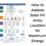
How to Assess Solar PV Array Location for Maximum Energy
A complete guide to battery bank enclosure and rack installation, including site verification, setup procedures, and safety practices for solar PV systems.
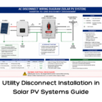
Utility Disconnect Installation in Solar PV Systems Guide
A step-by-step guide to utility disconnect installation in solar PV systems, including wiring, safety measures, and installation best practices.
Should You Replace Solar Panels with Solar Shingles?
Discover how solar batteries store excess energy, maximize your solar system’s efficiency, and provide reliable power during outages. Learn about the types, benefits, lifespan, and maintenance tips to make the most of your solar investment.
Ground Mounted Solar Systems: Complete Guide for Commercial & Industrial Projects in India
Ground mounted solar systems are ideal for commercial and industrial projects with available land. This guide explains cost, land requirement, installation process, and ROI in India.

Minimum Land Requirement for Solar Power Plants in India
Understanding the land requirement for solar plant projects in India is essential for accurate planning and approvals. This article explains minimum land needed per kW and MW, key influencing factors, and differences between rooftop and ground-mounted solar plants.
Solar Inverter Stand Installation: Step-by-Step Guide
A step-by-step guide to solar inverter stand installation as per drawings and manuals, ensuring proper alignment, stability, and safety.

Breakthrough in Solar Technology: 33.2% Efficient Perovskite-Silicon Cell
Scientists achieve a breakthrough in solar technology with a perovskite-silicon tandem cell reaching a record 33.2% efficiency for higher energy output.
How to Connect a Solar Panel to an MPPT Charge Controller: Step-by-Step Guide
This guide explains how to connect a solar panel to an MPPT charge controller step by step. Learn correct wiring, safety tips, and best practices to ensure efficient and reliable solar power performance.