In solar photovoltaic (PV) installations, understanding electrical connections is essential for safe and efficient system operation. One of the most important tools used by solar installers and engineers is the Single Line Diagram (SLD). It provides a simplified representation of the entire electrical system, showing how different components are connected and how power flows through the system.
A well-designed SLD helps in system planning, installation, troubleshooting, and maintenance. The ability to read and interpret SLDs is a fundamental skill for solar technicians to ensure proper system design and safety.
This blog offers a complete guide to SLD in solar PV systems, including design principles, commonly used symbols, and step-by-step instructions on how to read an SLD effectively.
What is a Single Line Diagram (SLD)?
A Single Line Diagram (SLD) is a simplified electrical drawing that represents the entire solar PV system using single lines and standard symbols. Instead of showing every wire, it uses one line to represent multiple conductors, making it easier to understand complex systems.
The SLD shows:
- Electrical components
- Connections between components
- Direction of power flow
- Protection devices
It is widely used in designing solar plant installations and analyzing solar electricity systems.
Importance of SLD in Solar PV Systems
SLDs play a crucial role in solar installation and maintenance.
Key benefits include:
- Simplifies complex electrical systems
- Helps in system design and planning
- Assists in troubleshooting faults
- Ensures safe installation practices
- Optimizes solar panel system cost
A properly designed SLD improves the efficiency and reliability of renewable solar systems.
Key Components Represented in an SLD
An SLD includes all major components of a solar PV system.
1. Solar PV Modules
- Represented as a source of DC power.
- They generate solar electricity from sunlight and are the starting point of the system.
2. String Combiner Box (SCB)
- Combines output from multiple solar panel strings.
- Includes protection devices such as fuses and isolators.
3. DC Isolator
- Used to disconnect the DC supply during maintenance or emergencies.
- Ensures safety during installation and servicing.
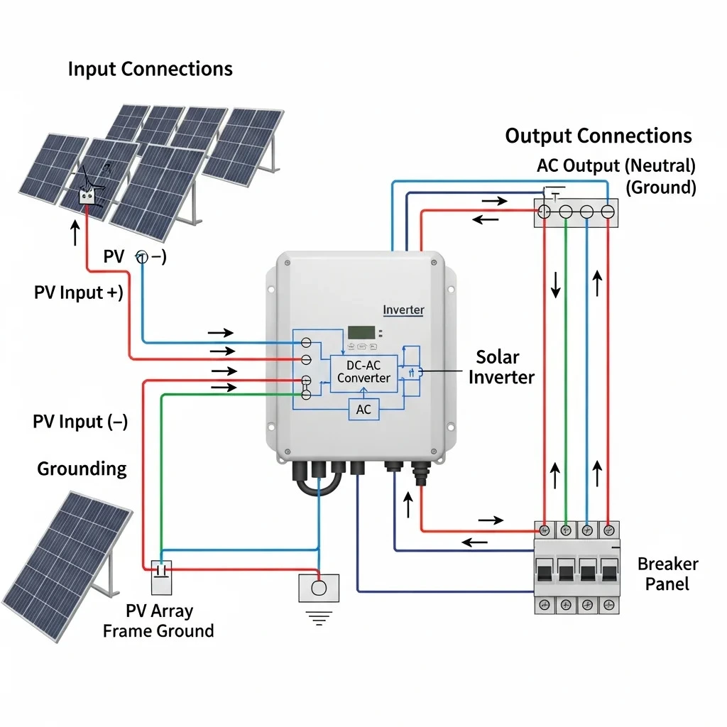
4. Solar Inverter
- Converts DC electricity into AC.
- Acts as the central component connecting solar panels to the load or grid.
5. AC Distribution Board (ACDB)
- Distributes AC power to different loads.
- Includes circuit breakers and protection devices.
6. Net Meter
- Measures electricity imported from and exported to the grid.
- Important for grid-connected systems under policies by the Ministry of New and Renewable Energy.
7. Grid Connection
- Represents the connection to the utility grid.
- Enables export of excess solar electricity.
8. Earthing System
- Ensures electrical safety by grounding the system.
- Protects against faults and lightning.
Common Symbols Used in SLD
SLDs use standardized symbols to represent components.
Some commonly used symbols include:
- Solar panel symbol – rectangle with diagonal lines
- Inverter symbol – box with DC/AC conversion marking
- Circuit breaker – switch symbol
- Ground (earthing) – vertical line with horizontal bars
- Meter – circular symbol
Understanding these symbols is essential for reading SLDs accurately.
Steps to Design an SLD for Solar PV System
Step 1 – Identify System Type
Determine whether the system is:
- Grid-connected
- Off-grid
- Hybrid
This affects the components included in the SLD.
Step 2 – Define System Capacity
Specify the solar plant capacity (e.g., 3 kW, 5 kW).
This helps determine component ratings and connections.
Step 3 – Arrange Components in Sequence
Typical sequence:
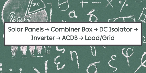
This shows the flow of solar electricity.
Step 4 – Add Protection Devices
Include:
- Circuit breakers
- Surge protection devices
- Isolators
These ensure system safety.
Step 5 – Include Earthing and Metering
Add:
- Earthing connections
- Net meter
- Monitoring system
These components are essential for safe and efficient operation.
Step 6 – Label All Components
Clearly label:
- Component names
- Ratings (kW, voltage, current)
- Cable specifications
Proper labeling improves clarity and usability.
How to Read an SLD (Step-by-Step)
Step 1 – Start from the Power Source
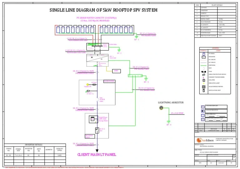
Begin with solar panels, which generate DC electricity.
Step 2 – Follow the Flow of Electricity
Trace the path from panels to inverter and then to load or grid.
Step 3 – Identify Key Components
Recognize:
- Inverter
- Distribution boards
- Protection devices
Step 4 – Check Protection Systems
Ensure the presence of circuit breakers, isolators, and earthing.
Step 5 – Understand Grid Interaction
Check how the system connects to the grid and net meter.
Impact of SLD on Solar Panel System Cost
A well-designed SLD helps:
- Optimize system design
- Reduce installation errors
- Improve equipment selection
- Lower solar installation charges
It ensures efficient use of resources and reduces the cost of solar per kWh installed.
Best Practices for SLD Design
- Use standard symbols and conventions
- Keep the diagram simple and clear
- Label all components accurately
- Include safety and protection devices
- Verify compliance with regulations
These practices improve renewable energy technology implementation.
Conclusion
The Single Line Diagram (SLD) is a vital tool in solar PV system design and installation. It simplifies complex electrical systems into an easy-to-understand format, allowing installers to visualize component connections and power flow. By understanding SLD design, symbols, and reading techniques, solar professionals can ensure safe, efficient, and reliable system performance.
Mastering SLD interpretation is a fundamental skill for solar technicians. Additionally, guidelines from the Ministry of New and Renewable Energy support standardized solar system design and implementation.
With proper SLD design and understanding, solar installers can optimize solar panel system cost, improve solar electricity generation, and support the growth of renewable solar solutions for solar energy for home use and commercial applications.
FAQs
Q1. What is the purpose of an SLD in solar PV systems?
Ans: An SLD provides a simplified representation of the electrical system, helping in design, installation, and troubleshooting.
Q2. What components are shown in a solar SLD?
Ans: It includes solar panels, inverter, combiner box, distribution boards, protection devices, and grid connection.
Q3. Why is an SLD important for installers?
Ans: It helps installers understand system connections and ensures safe and efficient installation.
Q4. How does an SLD affect solar panel system cost?
Ans: A clear SLD helps optimize design and reduce installation errors, lowering overall costs.
Q5. Is SLD required for all solar installations?
Ans: Yes, SLD is essential for proper planning and execution of both small and large solar systems.
Solar PV Fault Escalation & Troubleshooting Guide
A complete guide to escalating unresolved faults in solar PV systems, including troubleshooting procedures, documentation, supervisor notification, and technical support for efficient maintenance.
Rajasthan Rooftop Solar Subsidy: What Homeowners Need to Know
Rajasthan homeowners can save big with the 2025 rooftop solar subsidy. Learn about the updated rates, eligibility criteria, and benefits to make your switch to solar more affordable.
Updated Rates of Solar Subsidy in Delhi: Cost, Eligibility & Benefits
Discover the latest solar subsidy rates in Delhi for 2025. This guide explains the updated costs, eligibility criteria, and benefits to help you maximize savings on your rooftop solar installation.
Earthing and Lightning Protection Required for Solar Installation – Complete Guide for Solar Installers
Earthing and lightning protection are critical safety components in solar PV installations. This guide explains their importance, types, components, and best practices for solar installers.
Electrical Measuring Instruments Every Solar Installer Must Know
Solar installers rely on accurate electrical measurements for safe and efficient system performance. This guide explains the role of voltmeters, ammeters, digital multimeters, and clamp meters in solar installations.
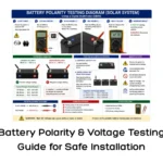
Battery Polarity & Voltage Testing Guide for Safe Installation
A complete guide to battery polarity and voltage testing, ensuring safe battery installation and reliable performance in solar PV systems.
China’s Solar Industry Poised for Continued Growth in 2023 and Beyond
China’s solar industry is set for continued growth in 2023 and beyond, driving global renewable energy expansion and technological advancements.
Agrovoltaics Innovation: Boosting Solar Energy While Supporting Farming
Explore agrovoltaics innovation: how combining solar energy with farming boosts efficiency, supports agriculture, and maximizes land use.