Open Circuit Voltage (Voc) is one of the most important electrical parameters measured during the installation, commissioning, inspection, troubleshooting, and maintenance of solar photovoltaic (PV) systems. It represents the maximum voltage produced by a solar PV module or string when no electrical load is connected to the circuit. Measuring Voc helps verify proper module operation, detect wiring errors, identify faulty modules, and confirm that the solar array is performing according to the manufacturer’s specifications.
Whether in residential rooftop systems, commercial solar installations, industrial plants, or utility-scale solar farms, regular measurement of open-circuit voltage is an essential preventive maintenance practice. It allows solar installers, commissioning engineers, EPC contractors, and operations and maintenance (O&M) professionals to identify abnormalities before they develop into major system failures. A significant deviation from the expected Voc value may indicate issues such as damaged modules, loose connections, incorrect string configuration, shading, or degradation.
Since solar PV systems generate direct current (DC) electricity whenever sunlight is available, measuring Voc requires strict adherence to electrical safety procedures. Using calibrated instruments, following manufacturer guidelines, and recording test results accurately are essential for obtaining reliable measurements and ensuring safe work practices.
Measuring open-circuit voltage is a fundamental test carried out during commissioning and maintenance to verify the electrical health and performance of solar PV modules and strings.
This comprehensive guide explains the meaning of open circuit voltage, factors affecting Voc, required tools, testing procedures, interpretation of results, safety precautions, and industry best practices.
What is Open Circuit Voltage (Voc)?
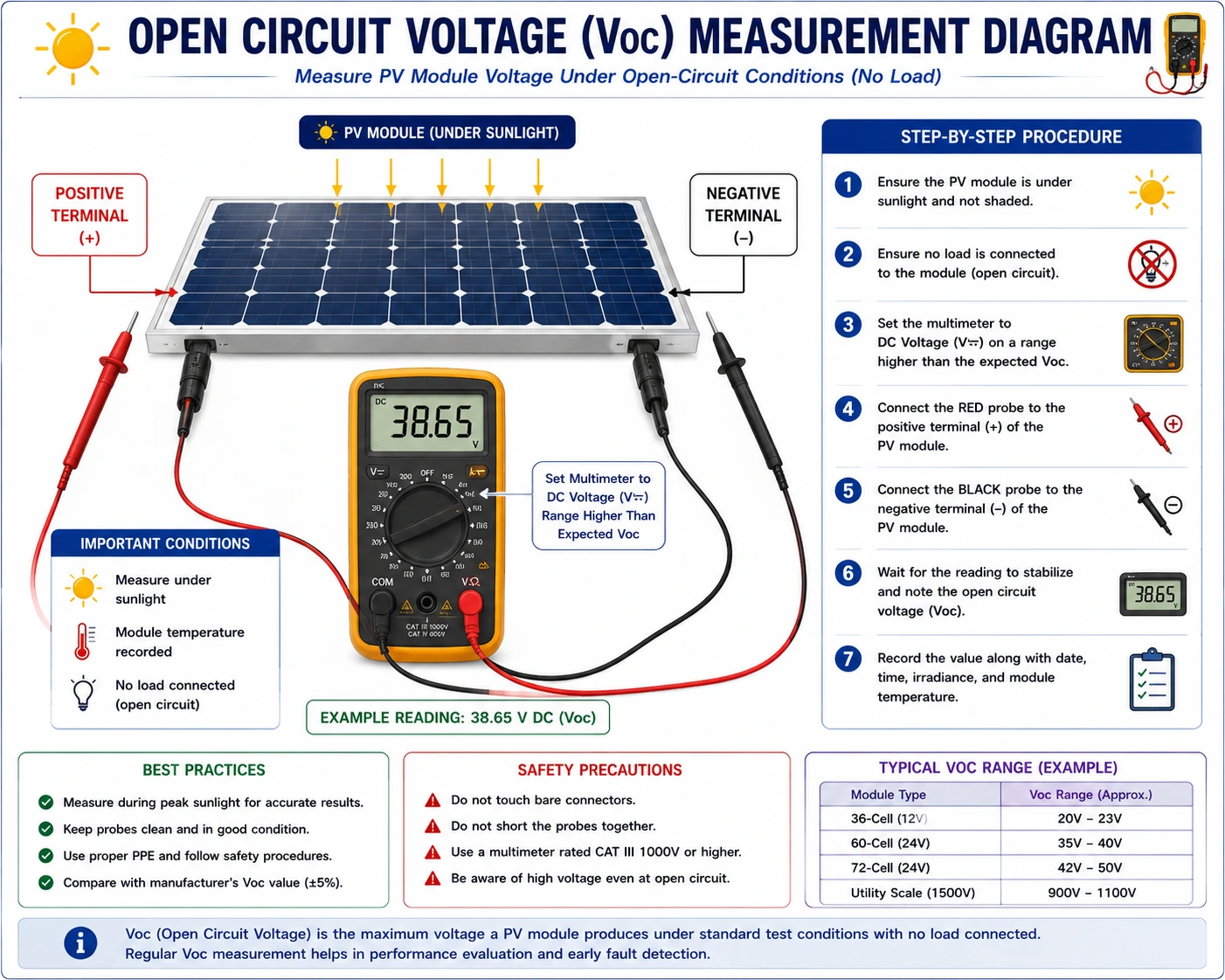
Open Circuit Voltage (Voc) is the voltage available at the terminals of a solar PV module or string when no load is connected and no current is flowing.
It represents the highest voltage the module can produce under existing environmental conditions.
Voc is typically specified by the manufacturer under Standard Test Conditions (STC), which include:
- Solar irradiance of 1000 W/m²
- Cell temperature of 25°C
- Air mass (AM) of 1.5
Actual field measurements may differ from STC values because environmental conditions vary.
Why is Measuring Open Circuit Voltage Important?
Voc measurement provides valuable information about the condition of the PV system.
It helps:
- Verify correct installation
- Detect faulty modules
- Identify wiring errors
- Confirm string configuration
- Support preventive maintenance
- Improve the renewable solar system reliability
- Assist in troubleshooting
- Validate commissioning results
Routine Voc measurements help prevent unexpected system failures.
Factors Affecting Open Circuit Voltage
Several environmental and operational factors influence Voc.
These include:
- Solar irradiance
- Module temperature
- Module age
- Cell degradation
- Partial shading
- Manufacturing tolerances
- Loose electrical connections
- Cable resistance
Understanding these factors is essential for accurate interpretation.
Typical Open Circuit Voltage Values
Voc varies depending on:
- Module technology
- Number of cells
- Manufacturer
- System design
For example:
PV Module Type | Typical Voc Range |
36-cell module | 20–23 V |
60-cell module | 36–40 V |
72-cell module | 44–50 V |
For strings, the total Voc is approximately the sum of the Voc values of all series-connected modules, adjusted for environmental conditions.
Always compare measured values with manufacturer specifications.
Tools Required for Measuring Voc
Proper testing requires suitable equipment.
Common tools include:
- Digital multimeter (DC voltage range)
- PV analyzer
- Clamp meter (for additional testing)
- Inspection checklist
- Temperature sensor
- Pyranometer (optional for irradiance measurement)
- Personal protective equipment (PPE)
Use calibrated instruments for accurate results.
Personal Protective Equipment (PPE)
Technicians should wear:
- Safety helmet
- Electrical insulating gloves
- Safety glasses
- Safety shoes
- Arc-rated protective clothing is required where
Safety is critical because PV modules generate voltage whenever exposed to sunlight.
Step-by-Step Procedure for Measuring Open Circuit Voltage
Step 1 – Review System Documentation
Before beginning:
Review:
- Electrical drawings
- Single-line diagrams
- Manufacturer specifications
- Previous inspection reports
This helps determine expected Voc values.
Step 2 – Verify Safe Working Conditions
Ensure:
- Good weather
- Safe rooftop access
- Proper fall protection
- Suitable lighting
- Electrical safety procedures are in place
Step 3 – Perform Visual Inspection
Inspect:
- PV modules
- DC cables
- Connectors
- Junction boxes
- Combiner boxes
Look for:
- Cracks
- Loose connectors
- Corrosion
- Damaged insulation
- Burn marks
Correct visible defects before electrical testing.
Step 4 – Isolate the Circuit
Disconnect the module or string according to approved procedures so that no electrical load is connected.
This creates the open-circuit condition required for measurement.
Follow lockout/tagout procedures where applicable.
Step 5 – Set the Multimeter
Configure the digital multimeter to measure:
- DC Voltage
Select an appropriate voltage range based on the expected system voltage.
Step 6 – Connect the Test Leads
Connect:
- Red probe to the positive terminal
- Black probe to the negative terminal
Ensure firm contact with the terminals. Avoid short-circuiting the conductors.
Step 7 – Record the Open Circuit Voltage
Read the displayed voltage.
Record:
- Voc value
- Module or string identification
- Date
- Time
- Weather conditions
- Irradiance (if measured)
- Module temperature
Documentation is essential for future comparisons.
Step 8 – Compare Results with Expected Values
Compare measured Voc with:
- Manufacturer specifications
- Design documents
- Previous maintenance records
Small variations are normal due to environmental conditions. Large deviations require further investigation.
Step 9 – Investigate Abnormal Results
Low Voc may indicate:
- Damaged cells
- Loose connectors
- Wiring errors
- Partial shading
- Moisture ingress
- Module degradation
Higher-than-expected values may result from:
- Very low module temperatures
- Incorrect string configuration
Further testing may be necessary.
Step 10 – Complete Documentation
Update the maintenance logbook with:
- Test results
- Observations
- Corrective actions
- Technician details
- Recommendations
Accurate records support preventive maintenance.
Common Causes of Low Open Circuit Voltage
Reduced Voc may result from:
- Cracked PV modules
- Cell degradation
- Loose electrical connections
- Incorrect wiring
- Corrosion
- Faulty connectors
- Water ingress
- Excessive shading
Prompt corrective action minimizes energy losses.
Conclusion
Measuring open circuit voltage is a fundamental electrical test that plays a vital role in the installation, commissioning, preventive maintenance, and troubleshooting of solar PV systems. Accurate Voc measurements help verify system integrity, identify electrical faults, confirm proper string configuration, and ensure that PV modules operate according to design specifications. Regular voltage testing also supports preventive maintenance by enabling early detection of degradation, loose connections, and damaged components before they significantly impact system performance.
Routine measurement of open-circuit voltage is an essential practice for solar installers, commissioning engineers, EPC contractors, and operations and maintenance professionals. Furthermore, following technical recommendations and electrical safety practices promoted by the Ministry of New and Renewable Energy, together with manufacturer guidelines, helps ensure safe, standards-compliant, and accurate testing of renewable solar systems.
By using calibrated instruments, maintaining detailed test records, considering environmental conditions during analysis, following safe testing procedures, and addressing abnormal voltage readings promptly, solar professionals can optimize solar panel system cost, maximize renewable solar system reliability, improve long-term energy generation, and ensure the continued success of residential, commercial, industrial, and utility-scale solar energy projects.
FAQs
Q1. What is the open-circuit voltage (Voc) in a solar PV module?
Ans: Open circuit voltage (Voc) is the maximum voltage produced by a solar PV module or string when no electrical load is connected and no current is flowing.
Q2. Why is measuring Voc important?
Ans: Measuring Voc helps verify correct installation, detect faulty modules, identify wiring errors, confirm string configuration, and assess the electrical health of the solar PV system.
Q3. Which instrument is commonly used to measure open-circuit voltage?
Ans: A calibrated digital multimeter set to the DC voltage range is the most commonly used instrument. PV analyzers may also be used for advanced testing.
Q4. Why can measured Voc differ from the manufacturer’s rated value?
Ans: The manufacturer’s rating is specified under Standard Test Conditions (STC). Actual field measurements vary depending on solar irradiance, module temperature, weather conditions, module age, and installation environment.
Q5. What should be recorded during a Voc test?
Ans: Technicians should record the measured Voc, module or string identification, date, time, weather conditions, irradiance (if measured), module temperature, observations, technician details, and any corrective actions in the maintenance logbook.

Eco-Friendly Solar Panels: The Future of Sustainable Power
Eco-friendly solar panels are revolutionizing the way we generate clean energy. This blog explores their benefits, sustainable materials, and role in reducing carbon footprint while providing efficient energy solutions for residential, industrial, and commercial use. Learn why investing in eco-friendly solar technology is the future of sustainable power.

Benefits of Solar Energy: Why Switching to Solar Makes Sense
Switching to solar energy offers numerous benefits, from lowering electricity bills to reducing your carbon footprint. This guide explores how solar power supports sustainable living, provides cost savings, and creates a cleaner environment for homes, businesses, and industries. Learn why adopting solar energy is not just smart, but essential for a greener future.
Solar PV Conduit & Cable Routing Plan Guide
A complete guide to preparing solar PV conduit and cable routing plans, including layout design, routing methods, and installation best practices.
Rajasthan Rooftop Solar Subsidy: What Homeowners Need to Know
Rajasthan homeowners can save big with the 2025 rooftop solar subsidy. Learn about the updated rates, eligibility criteria, and benefits to make your switch to solar more affordable.
Solar PV Fault Escalation & Troubleshooting Guide
A complete guide to escalating unresolved faults in solar PV systems, including troubleshooting procedures, documentation, supervisor notification, and technical support for efficient maintenance.

Difference Between Inverter and Solar Inverter: A Complete Comparison
Confused between an inverter and a solar inverter? This guide explains their key differences, working principles, advantages, and which option is best for your home or business.
500 kW Solar System Price in Indore: Complete Industrial Guide
Planning to install a 500 kW solar power plant in Indore? Discover the complete cost details, government subsidy options, and potential savings for industries in 2025.
Important Factors Deciding the Type of Solar PV System to be Installed
A solar site assessment helps installers evaluate location, shading, structure, and energy requirements before installation. This guide explains the essential steps for accurate solar system planning.