Solar photovoltaic (PV) systems generate clean electricity and have become an important part of the transition toward renewable energy and solar energy. From residential rooftop installations to commercial and industrial projects and large utility-scale solar plants, PV systems contain numerous electrical components that must be installed, operated, tested, and maintained safely.
Although solar PV systems are designed with multiple protective devices, electrical hazards remain one of the most important occupational risks associated with their installation and operation. PV modules can produce DC electricity whenever they are exposed to sunlight, while inverters and associated equipment may involve AC voltages capable of causing severe injury or fatal electric shock. Additional risks include arc flash, short circuits, incorrect polarity, damaged insulation, poor grounding, loose connections, and improperly rated electrical equipment.
Electrical hazard identification is therefore an essential activity before and during every stage of a solar project. Workers should be able to recognize potential electrical hazards, understand the conditions that can create them, and follow appropriate procedures to eliminate or control the associated risks.
A systematic approach to electrical safety helps protect personnel, prevent fires and equipment damage, reduce system downtime, and maintain reliable solar electricity generation. It also contributes to better installation quality and the long-term reliability of a solar plant.
This guide explains the major electrical hazards associated with solar PV systems, how to identify them, appropriate preventive measures, inspection practices, and the responsibilities of solar professionals.
What Are Electrical Hazards?
An electrical hazard is a condition involving electricity that can potentially cause:
– Electric shock
– Burns
– Arc flash injuries
– Arc blast
– Fire
– Equipment damage
– Electrical system failure
– Fatal injury
In solar PV installations, electrical hazards can occur on both the DC and AC sides of the system.
The DC side generally includes:
– PV modules
– String circuits
– DC cables
– Connectors
– Combiner boxes
– DC isolators
– DC surge protection devices
The AC side may include:
– Inverters
– AC cables
– Distribution boards
– Circuit breakers
– Switchgear
– Transformers
– Grid connection equipment
Understanding both sides of the system is essential for safe working practices.
Why Is Electrical Hazard Identification Important?
Electrical hazard identification helps organizations:
– Protect workers from electric shock.
– Prevent electrical fires.
– Reduce equipment damage.
– Avoid unexpected system shutdowns.
– Improve installation quality.
– Maintain regulatory compliance.
– Reduce maintenance costs.
– Improve solar electricity generation.
– Increase the reliability of renewable solar systems.
Identifying hazards before work begins is much safer than discovering them after an accident.
Major Electrical Hazards in Solar PV Systems
1. Electric Shock
Electric shock is one of the most serious risks associated with PV installations.
PV modules continue producing electricity whenever sufficient sunlight is available. Therefore, simply switching off an inverter does not necessarily make the entire PV array electrically dead.
Electric shock can occur when a worker:
– Touches an exposed conductor.
– Handles damaged cables.
– Works on energized equipment.
– Uses inappropriate tools.
– Makes contact with faulty equipment.
– Works with wet hands or in wet conditions.
Preventive Measures
Workers should:
– Identify energized circuits before starting work.
– Follow approved isolation procedures.
– Use appropriate electrical PPE.
– Use insulated tools where required.
– Avoid touching exposed conductors.
– Verify electrical conditions using suitable test equipment.
2. DC Voltage Hazards
PV modules produce DC voltage whenever exposed to sunlight.
A string containing multiple modules connected in series can produce substantially higher voltage than an individual module.
Potential hazards include:
– Electric shock
– Arc formation
– Burns
– Equipment damage
– Fire
Mitigation
– Follow manufacturer instructions.
– Use correctly rated DC equipment.
– Avoid disconnecting connectors under load unless the connector and procedure specifically permit it.
– Verify voltage before working on circuits.
– Use appropriate DC isolation equipment.
3. AC Electrical Hazards
The inverter converts DC electricity from the PV array into AC electricity. The AC side may contain hazardous voltages capable of causing severe injury.
Hazards may occur at:
– Inverter AC terminals
– Distribution boards
– Circuit breakers
– Switchgear
– Transformers
– Grid connection points
Mitigation
Only authorized and appropriately trained personnel should work on these systems. Isolation and verification procedures should be completed before maintenance.
4. Arc Flash
An arc flash can occur when electrical current travels through an unintended path through air or another conductive medium.
It can produce:
– Extremely high temperatures
– Intense light
– Pressure waves
– Molten metal
– Severe burns
– Equipment damage
Possible causes include:
– Loose connections
– Short circuits
– Damaged insulation
– Incorrect switching
– Faulty equipment
– Conductive tools contacting energized components
Preventive Measures
– Maintain electrical equipment properly.
– Use correctly rated components.
– Inspect connections.
– Follow safe switching procedures.
– Maintain appropriate working clearances.
– Use suitable PPE based on the electrical risk assessment.
5. Short Circuits
A short circuit occurs when current flows through an unintended low-resistance path.
In a PV system, short circuits may result from:
– Damaged insulation
– Incorrect wiring
– Loose conductors
– Water ingress
– Faulty connectors
– Improper installation
Short circuits can cause overheating, equipment damage, and fire.
Mitigation
– Inspect cables regularly.
– Maintain correct polarity.
– Use appropriately rated protection devices.
– Replace damaged conductors.
– Keep connections clean and secure.
6. Incorrect Polarity
Incorrect polarity can occur when positive and negative conductors are connected incorrectly.
This may result in:
– Equipment malfunction
– Reverse current
– Component damage
– Fault conditions
– Reduced system performance
Mitigation
Polarity should be verified using an appropriate meter before connecting circuits. Do not rely solely on cable color or labels; physical verification should be performed according to the applicable procedure.
7. Damaged Cable Insulation
PV cables are exposed to sunlight, heat, moisture, mechanical stress, animals, and environmental conditions.
Damage may occur because of:
– Abrasion
– Improper cable routing
– Rodent activity
– UV exposure
– Excessive bending
– Sharp edges
– Poor installation practices
Damaged insulation can expose conductors and create shock, short-circuit, or fire hazards.
Mitigation
– Inspect cables regularly.
– Maintain appropriate cable support.
– Avoid sharp bends.
– Protect cables from mechanical damage.
– Replace damaged cables promptly.
8. Loose Electrical Connections
Loose terminals and connectors can increase electrical resistance and generate heat.
Over time, this may cause:
– Overheating
– Hot spots
– Insulation deterioration
– Arcing
– Fire
– Equipment failure
Mitigation
Connections should be installed and maintained according to manufacturer specifications. Where specified, appropriate torque tools should be used and inspection records maintained.
9. Poor Grounding and Bonding
Grounding and bonding are essential components of electrical safety.
Improper grounding may increase the risk of:
– Electric shock
– Equipment damage
– Fault-current hazards
– Lightning-related damage
All applicable grounding and bonding requirements should be followed for the particular PV system.
Mitigation
– Inspect grounding conductors.
– Verify bonding connections.
– Check continuity where required.
– Inspect for corrosion.
– Use appropriately sized conductors.
– Maintain connections according to applicable standards and design requirements.
10. Faulty Circuit Breakers and Fuses
Protective devices such as circuit breakers and fuses help protect electrical circuits against abnormal current conditions. A faulty, incorrectly rated, or improperly installed protective device may fail to provide the required protection.
Inspection Should Include
– Correct rating
– Physical condition
– Proper installation
– Signs of overheating
– Signs of arcing
– Correct operation
Defective protective devices should be replaced by qualified personnel.
11. Water and Electrical Equipment
Water and electricity create a particularly dangerous combination.
Electrical hazards can increase during:
– Rainfall
– Flooding
– Water leakage
– Condensation
– Equipment washing
Water ingress into electrical enclosures may result in:
– Short circuits
– Corrosion
– Insulation failure
– Electric shock
– Equipment damage
Mitigation
– Use appropriately rated enclosures.
– Inspect seals and cable glands.
– Prevent water accumulation.
– Never work on electrical equipment in unsafe wet conditions.
– Follow manufacturer cleaning procedures.
12. Overheating
Electrical components can overheat because of:
– Excessive current
– Loose connections
– Undersized conductors
– Poor ventilation
– Overloaded equipment
– Faulty components
Overheating may eventually lead to insulation failure or fire.
Mitigation
Regularly inspect:
– Inverters
– Combiner boxes
– Switchboards
– Cable connections
– Circuit breakers
– Transformers
Thermal inspection may also be used where appropriate.
13. Battery Electrical Hazards
Solar PV systems with energy storage introduce additional electrical risks.
Battery systems can involve:
– High DC currents
– Short-circuit hazards
– Electrical shock
– Overheating
– Fault currents
Battery maintenance should follow the manufacturer’s instructions and the site’s approved safety procedures.
14. Lightning and Surge Hazards
Solar PV installations are exposed to outdoor environmental conditions and may be vulnerable to lightning-related surges.
Surges can damage:
– PV modules
– Inverters
– Monitoring systems
– Communication equipment
– Other electrical components
Mitigation
Depending on system design and applicable requirements:
– Install appropriate surge protection.
– Maintain grounding systems.
– Provide lightning protection where required.
– Inspect protective devices periodically.
15. Backfeed and Unexpected Energization
A circuit may become energized from another source even after one source has been disconnected.
Potential sources include:
– Grid supply
– PV array
– Battery storage
– Generator
– Other interconnected electrical systems
Workers must identify all possible energy sources before beginning work.
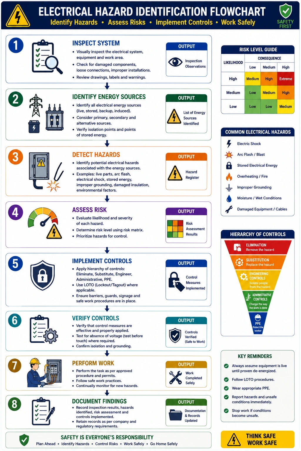
How to Identify Electrical Hazards
A structured inspection can be performed using the following steps.
Step 1: Review the System Design
Understand:
– Single-line diagrams
– Equipment ratings
– Circuit configuration
– Isolation points
– Grounding arrangements
– Energy sources
Step 2: Conduct a Visual Inspection
Look for:
– Exposed conductors
– Damaged cables
– Burn marks
– Loose connections
– Corrosion
– Missing covers
– Damaged enclosures
Step 3: Identify Energy Sources
Determine whether the system contains:
– PV-generated DC
– Utility AC
– Battery energy
– Generator supply
– Other connected sources
Step 4: Assess the Risk
Consider:
– Probability of occurrence
– Potential severity
– Exposure duration
– Number of workers affected
Step 5: Implement Controls
- Apply appropriate controls before work begins.
Step 6: Verify the Controls
- Confirm that the hazard has been adequately controlled before proceeding.
Electrical Safety Inspection Checklist
A basic inspection should consider:
Inspection Area | What to Check |
PV modules | Visible damage and electrical condition |
DC cables | Insulation, routing and physical damage |
Connectors | Proper engagement and condition |
Combiner boxes | Enclosure, connections and protection |
Inverters | Alarms, ventilation and electrical connections |
AC cables | Insulation and routing |
Grounding | Conductors, connections and bonding |
Circuit breakers | Rating and physical condition |
Fuses | Correct rating and condition |
Switchgear | Signs of overheating or damage |
Batteries | Connections, condition and protection |
Labels | Correct electrical identification |
Role of Lockout/Tagout
Lockout/Tagout (LOTO) is an important method of controlling hazardous energy during maintenance.
A typical process involves:
- Identifying energy sources.
- Shutting down equipment.
- Isolating energy sources.
- Applying locks and tags.
- Verifying isolation.
- Performing the work.
- Removing controls according to procedure.
- Restoring the equipment safely.
The exact procedure should always follow the organization’s approved safety program and equipment-specific requirements.
Conclusion
Identifying electrical hazards is one of the most important safety activities associated with solar photovoltaic installations. Because PV modules can generate DC electricity whenever sunlight is available, electrical risks can exist even when portions of the system have been shut down. In addition, inverters, distribution equipment, transformers, batteries, and grid connections introduce further AC and DC hazards that require careful assessment and control.
Solar professionals should systematically inspect installations for exposed conductors, damaged insulation, loose connections, incorrect polarity, inadequate grounding, faulty protective devices, overheating, water ingress, and other abnormal conditions. Before performing electrical work, all relevant energy sources should be identified and controlled using the organization’s approved procedures. Appropriate testing, isolation, Lockout/Tagout practices, qualified personnel, suitable tools, and task-specific PPE are essential components of safe work.
Electrical safety should also be treated as an ongoing process rather than a one-time installation activity. Regular inspection, preventive maintenance, accurate documentation, incident reporting, and employee training help identify developing problems before they become serious failures.
By effectively identifying and mitigating electrical hazards, solar EPC companies, installers, and O&M teams can protect workers, reduce equipment damage, improve system availability, and maximize solar electricity generation. These practices also support better lifecycle economics by reducing avoidable maintenance expenses, protecting investments in solar energy, improving the cost of solar per kWh installed, and supporting a lower solar installation cost per kWh.
Ultimately, effective electrical hazard management is essential for creating safe, reliable, and efficient renewable solar installations—from solar energy for home use and commercial rooftops to large industrial facilities and utility-scale solar plants. A strong electrical safety culture protects people first while simultaneously supporting the long-term performance and sustainability of solar PV systems.
FAQs
Q1. How can electrical hazards be identified before maintenance?
Ans: Workers should review system documentation, identify all energy sources, conduct a visual inspection, assess potential hazards, follow approved isolation procedures, and verify electrical conditions using suitable test equipment before beginning work.
Q2. Is PPE enough to protect workers from electrical hazards?
Ans: No. PPE is an important final layer of protection, but it should be used together with engineering controls, isolation procedures, safe work practices, appropriate equipment, training, and risk assessment.
Q3. What electrical components should be inspected regularly in a solar PV system?
Ans: Depending on the system design, inspections may include PV modules, DC cables, connectors, combiner boxes, isolators, inverters, AC cables, circuit breakers, fuses, switchgear, grounding conductors, surge protection devices, batteries, and electrical enclosures.
Q4. How do electrical hazards affect solar electricity generation?
Ans: Electrical faults can cause inverter shutdowns, equipment damage, string failures, fires, and extended downtime. Identifying and correcting hazards early helps maintain reliable solar electricity generation.
Q5. How does electrical hazard identification affect solar installation cost?
Ans: Preventive identification can reduce equipment damage, emergency repairs, downtime, and premature component replacement. Over the system lifecycle, this can contribute to a lower solar installation cost per kWh and cost of solar per kWh installed.
Fall Protection for Solar PV Systems
A complete guide to inspecting and installing fall protection systems for solar PV projects, helping protect workers during rooftop installation, maintenance, and other work at height.
Difference Between an On-Grid Inverter and a Hybrid Solar Inverter
Confused between an on-grid inverter and a hybrid solar inverter? This blog explains their differences, advantages, and which solar inverter is right for you.

New Loan Scheme for solar rooftop projects by IREDA
Solar installation for petrol pumps offers huge savings and energy independence. This 2025 guide explains system cost, subsidy, ROI, and installation process.
EIB Green Hydrogen India: €1 Billion Investment to Boost Clean Energy Transition
The European Investment Bank (EIB), the bank of the European Union, has joined forces with the India Hydrogen Alliance (IH2A) to increase support for the development of green hydrogen projects across India.
How to Maintain Solar Power System for Homes, Industries & Commercial Buildings
A solar power generating system converts sunlight into electricity for residential, industrial, and commercial use. This blog explains the components, working, and benefits of solar systems, helping you understand how to harness solar energy efficiently and sustainably.
Solar Power System Efficiency: How to Calculate for Residential, Industrial & Commercial Use
Understand and measure your solar system’s performance. Maximize energy output at home, industrial units, and commercial buildings
End of Rooftop Solar Subsidy for Industrial & Commercial Consumers: What You Need to Know
The rooftop solar subsidy for industrial and commercial consumers is coming to an end. This guide explains the implications for businesses, updated policies, and strategies to adopt solar power without relying on subsidies.
Solar Sector Growth in India Slows as Investments Decline in Q1 2023
India’s solar sector experiences an investment slowdown in Q1 2023, reflecting challenges in funding and growth for renewable energy projects.