Safety is one of the most critical aspects of any solar photovoltaic (PV) installation. While solar modules, inverters, batteries, and mounting structures receive significant attention during design and installation, the effectiveness of the grounding system and insulation integrity ultimately determines the long-term safety, reliability, and performance of the solar power plant.
Improper grounding can expose personnel and equipment to electric shock hazards, fault currents, lightning damage, and fire risks. Similarly, poor insulation can lead to leakage currents, energy losses, equipment malfunction, inverter faults, and premature system failure. For this reason, verifying system grounding and measuring insulation resistance are essential activities during installation, commissioning, troubleshooting, and maintenance of solar PV systems.
Whether the project involves a residential rooftop system, commercial solar installation, industrial solar plant, or utility-scale renewable solar project, proper grounding verification and insulation resistance testing ensure compliance with safety standards and improve overall system performance.
Grounding verification and insulation testing are mandatory quality assurance procedures that support safe solar electricity generation and long-term renewable energy technology performance.
This comprehensive guide explains the importance of system grounding, insulation resistance testing procedures, required tools, safety precautions, industry best practices, and common mistakes to avoid.
Understanding Grounding in Solar PV Systems
Grounding refers to the intentional connection of electrical equipment and conductive components to the earth.
The primary objectives of grounding are:
- Protect personnel from electric shock
- Dissipate fault currents safely
- Protect equipment from damage
- Improve system reliability
- Reduce lightning-related risks
A properly grounded solar PV system is essential for safe operation and regulatory compliance.
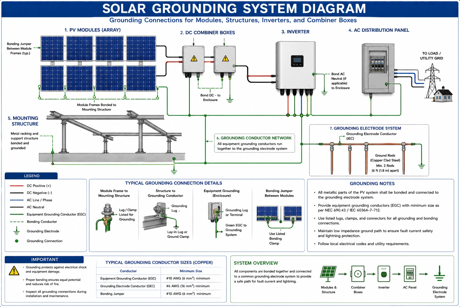
Components That Require Grounding
Grounding should be provided for:
Solar Module Frames
- Metal module frames must be electrically bonded and grounded.
Mounting Structures
- All metallic support structures should be connected to the grounding network.
Inverters
- Inverters require grounding according to manufacturer specifications.
Combiner Boxes
- Both DC and AC combiner boxes should be grounded.
Battery Systems
- Battery racks and enclosures require grounding.
Electrical Panels
- Distribution panels and disconnects should be connected to the grounding system.
Why Grounding Verification is Important
Grounding verification ensures that the installed grounding system functions correctly.
Benefits include:
- Improved personnel safety
- Reduced equipment damage
- Enhanced fault protection
- Better lightning protection
- Compliance with project specifications
Failure to verify grounding may result in:
- Shock hazards
- Equipment failures
- Increased maintenance costs
- Reduced renewable solar system reliability
Understanding Insulation Resistance
Insulation resistance measures the ability of insulation materials to resist electrical current flow.
High insulation resistance indicates:
- Good cable condition
- Proper equipment insulation
- Reduced leakage current
Low insulation resistance may indicate:
- Damaged insulation
- Moisture ingress
- Aging cables
- Installation defects
Why Insulation Resistance Testing is Important
Insulation resistance testing helps identify hidden electrical problems before system energization.
Benefits include:
- Preventing equipment failures
- Improving system safety
- Detecting cable damage
- Reducing maintenance costs
- Optimizing solar panel system cost
Applications of Grounding Verification and Insulation Testing
These tests are commonly performed during:
Installation
- Verification before commissioning.
Commissioning
- Final system acceptance testing.
Maintenance
- Periodic inspections and performance evaluations.
Troubleshooting
- Fault identification and diagnosis.
Tools Required for Grounding Verification
1. Earth Resistance Tester
- The primary instrument used to measure grounding system effectiveness.
Functions
- Measures earth resistance
- Verifies grounding performance
Applications
- Ground rod testing
- Earthing system inspection
2. Digital Multimeter
Used for:
- Continuity checks
- Voltage measurements
- Grounding verification
3. Continuity Tester
- Verifies electrical continuity between grounded components.
4. Clamp Ground Resistance Tester
- Allows ground resistance measurements without disconnecting grounding conductors.
Tools Required for Insulation Resistance Testing
1. Insulation Resistance Tester (Megger)
- The most common instrument used for insulation testing.
Functions
Measures the insulation resistance between:
- Conductors
- Conductors and ground
- Electrical equipment and earth
2. Digital Multimeter
- Used for preliminary electrical checks before insulation testing.
3. Test Leads and Adapters
- Provide safe and reliable test connections.
Step-by-Step Procedure for Grounding Verification
Step 1 – Review Grounding Design Documents
Examine:
- Earthing layout drawings
- Single Line Diagrams (SLD)
- Equipment grounding requirements
Step 2 – Visual Inspection
Inspect:
- Ground rods
- Ground conductors
- Bonding connections
- Corrosion protection
Verify that all components are installed according to design specifications.
Step 3 – Verify Grounding Continuity
Check continuity between:
- Module frames
- Mounting structures
- Inverters
- Combiner boxes
- Grounding conductors
All connections should demonstrate proper electrical continuity.
Step 4 – Measure Earth Resistance
Use an earth resistance tester to determine grounding effectiveness. The measured value should comply with project requirements and applicable standards.
Step 5 – Document Results
Record:
- Test locations
- Measured values
- Observations
- Corrective actions if required
Step-by-Step Procedure for Insulation Resistance Testing
Step 1 – De-Energize the System
Before testing:
- Disconnect power sources
- Follow lockout/tagout procedures
Safety must always be the first priority.
Step 2 – Inspect Equipment
Check for:
- Physical damage
- Moisture ingress
- Cable defects
Step 3 – Isolate Components
- Disconnect sensitive equipment if required by manufacturer instructions.
Step 4 – Connect the Insulation Resistance Tester
Connect test leads according to the testing procedure.
Common test configurations include:
- Positive conductor to ground
- Negative conductor to ground
- Positive conductor to negative conductor
Step 5 – Apply Test Voltage
Typical test voltages depend on system design and equipment ratings. The insulation tester applies a controlled voltage and measures resistance.
Step 6 – Record Insulation Resistance Values
Document:
- Test location
- Applied voltage
- Measured resistance
- Environmental conditions
Step 7 – Analyze Results
Compare measurements against project specifications and manufacturer recommendations. Low resistance values may require further investigation.
Factors Affecting Insulation Resistance Measurements
Several factors influence insulation resistance results:
Temperature
- Higher temperatures may reduce measured resistance.
Moisture
- Water ingress significantly lowers insulation resistance.
Dust and Contamination
- Surface contamination can affect measurements.
Cable Age
- Older cables may exhibit reduced insulation performance.
Acceptable Insulation Resistance Levels
Acceptable values vary depending on:
- System voltage
- Equipment type
- Applicable standards
- Manufacturer specifications
Installers should always follow project-specific requirements.
Conclusion
Verifying system grounding and measuring insulation resistance are fundamental quality assurance and safety procedures in every solar PV installation. These tests help identify hidden faults, protect personnel from electrical hazards, improve equipment reliability, and ensure compliance with project specifications.
Grounding and insulation testing play a vital role in safe solar electricity generation and long-term renewable energy technology performance. Furthermore, following recommendations and guidelines promoted by the Ministry of New and Renewable Energy helps ensure that solar installations meet industry safety and quality standards.
By conducting thorough grounding verification, performing accurate insulation resistance testing, maintaining proper documentation, and following established best practices, solar installers and EPC professionals can optimize solar panel system cost, enhance renewable solar system reliability, and support the successful operation of residential, commercial, industrial, and utility-scale solar projects.
FAQs
Q1. Why is grounding important in solar PV systems?
Ans: Grounding protects personnel and equipment by safely directing fault currents to earth and reducing electrical hazards.
Q2. What is insulation resistance testing?
Ans: It is a test used to evaluate the condition of electrical insulation and identify potential leakage paths or insulation failures.
Q3. Which tool is used for insulation resistance testing?
Ans: An insulation resistance tester, commonly known as a Megger, is used for this purpose.
Q4. When should insulation resistance testing be performed?
Ans: Testing is typically conducted during installation, commissioning, maintenance, and troubleshooting activities.
Q5. Why should Earth’s resistance be measured?
Ans: Earth resistance measurements verify the effectiveness of the grounding system and ensure compliance with safety requirements.
Different Components of a Solar PV System: Importance and Operation
Earthing and lightning protection are critical safety components in solar PV installations. This guide explains their importance, types, components, and best practices for solar installers.
New IREDA Loan Scheme for Solar Rooftop Projects: Benefits, Eligibility & Interest Rates
India’s renewable energy push gets a major boost with the new IREDA loan scheme for solar rooftop projects. This scheme offers low-interest financing, simplified approvals, and better support for residential, commercial, and industrial consumers. Here’s a detailed look at its benefits, eligibility, interest rates, and how to apply for funding.
What Is Solar Panel Efficiency? Meaning & Impact on Power Generation
Solar panel efficiency refers to how effectively a solar panel converts sunlight into usable electricity. This guide explains what solar panel efficiency means, why it matters, and how it directly impacts your solar system’s power output, space requirements, and overall performance.
Agrivoltaics: Merging Solar Power with Farming
Discover how solar batteries store excess energy, maximize your solar system’s efficiency, and provide reliable power during outages. Learn about the types, benefits, lifespan, and maintenance tips to make the most of your solar investment.
Data Acquisition System Calibration in Solar PV Plants
A complete guide to solar PV data acquisition system calibration, ensuring accurate monitoring, reliable data collection, and effective performance analysis.
Workplace Safety Incident Reporting Guide for Solar PV
A complete guide to establishing and following safe work procedures in solar PV systems, ensuring worker safety during installation, testing, commissioning, operation, and maintenance.

6 Upcoming Renewable Energy Events in India You Should Attend
The World Environment Expo, 2022 is a business platform that allows national and international equipment
Electrical Hazards in Solar PV Systems Guide
A complete guide to identifying electrical hazards in solar PV systems, covering shock, arc flash, DC voltage, wiring, grounding, and electrical fire risks.