
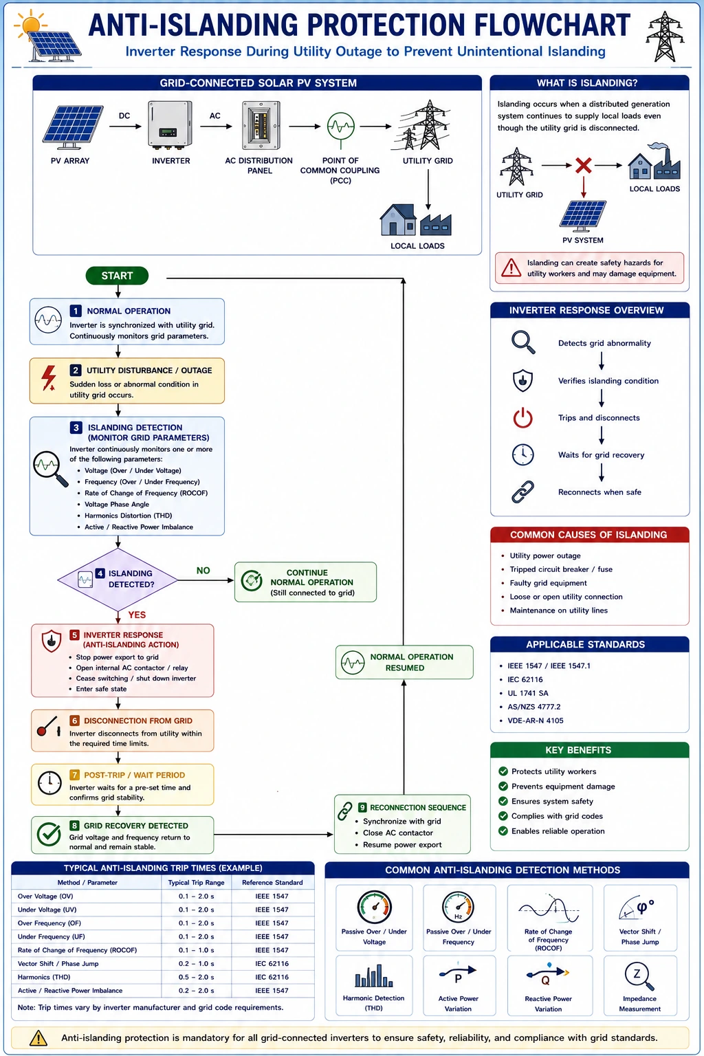
Grid-connected solar photovoltaic (PV) systems are designed to operate in synchronization with the utility power grid. Under normal operating conditions, the solar inverter continuously monitors the utility voltage, frequency, and phase before exporting electricity. However, when a utility outage occurs due to maintenance, equipment failure, or unforeseen events, the solar PV system must immediately stop supplying power to the disconnected section of the grid. This safety feature is known as anti-islanding or unintentional islanding protection.
The Unintentional Islanding Functionality Test is a critical commissioning and maintenance procedure performed to verify that the inverter correctly detects a loss of grid supply and disconnects from the utility within the time specified by applicable standards and manufacturer guidelines. This test protects utility personnel, maintenance crews, consumers, electrical equipment, and the integrity of the electrical network.
Failure of anti-islanding protection can create dangerous conditions where a disconnected section of the grid remains energized by the solar PV system. Such situations may expose utility workers to electric shock, damage equipment, interfere with restoration activities, and violate utility interconnection requirements.
Testing the anti-islanding function is an essential part of solar PV commissioning, inspection, and periodic maintenance to ensure safe renewable solar system operation.
This comprehensive guide explains the principles of unintentional islanding, testing procedures, required equipment, documentation, safety precautions, troubleshooting methods, and industry best practices.
What is Unintentional Islanding?
Unintentional islanding occurs when a portion of the electrical distribution network becomes electrically isolated from the utility grid but continues to receive power from one or more distributed generation sources, such as solar PV systems.
In this situation:
- The utility grid is disconnected.
- The solar inverter continues supplying electricity.
- Utility workers may incorrectly assume the line is de-energized.
Modern grid-tied inverters are designed to detect this condition and automatically disconnect.
What is Anti-Islanding Protection?
Anti-islanding protection is a safety feature built into grid-connected inverters that continuously monitors utility grid conditions.
If abnormal conditions are detected, the inverter:
- Stops exporting power.
- Disconnects from the grid.
- Waits until normal utility conditions return.
- Reconnects only after meeting specified reconnection criteria.
This functionality is mandatory in most grid-connected solar PV installations.
Why is the Unintentional Islanding Test Important?
Testing verifies that the inverter responds correctly during a simulated utility outage.
Benefits include:
- Protecting utility personnel
- Preventing electrical hazards
- Ensuring regulatory compliance
- Protecting inverter equipment
- Supporting the reliable operation of renewable solar systems
- Confirming proper commissioning
Objectives of the Anti-Islanding Test
The primary objectives include:
Safety Verification
Ensure the inverter disconnects immediately after grid loss.
Functional Verification
Confirm proper anti-islanding operation.
Standards Compliance
Verify compliance with applicable utility and safety requirements.
Equipment Protection
Prevent damage during abnormal operating conditions.
Commissioning Documentation
Record system performance during testing.
How Anti-Islanding Protection Works
The inverter continuously monitors:
- Grid voltage
- Frequency
- Phase angle
- Grid impedance (depending on inverter design)
When utility parameters exceed allowable limits, the inverter automatically disconnects from the grid. Once utility power returns and remains stable for the required reconnection delay, the inverter resumes operation.
Components Involved in the Test
Several components participate during testing.
1. Solar PV Array
Provides DC power to the inverter.
2. Grid-Tied Inverter
Detects abnormal grid conditions and disconnects.
3. Utility Disconnect Switch
Used to simulate grid loss.
4. AC Distribution Panel
Provides electrical distribution during testing.
5. Energy Meter
Confirms cessation and resumption of power export.
6. Monitoring System
Records inverter events and operational status.
Standards Governing Anti-Islanding Protection
Testing should comply with applicable standards and utility requirements.
Depending on the project location, relevant standards may include:
- IEC standards
- IEEE interconnection standards
- National electrical regulations
- Utility interconnection requirements
- Manufacturer specification
Always follow local regulations and project documentation.
Equipment Required for Testing
Typical testing equipment includes:
- Digital multimeter
- Clamp meter
- Power quality analyzer (if required)
- Commissioning checklist
- Stopwatch or timer
- Personal protective equipment (PPE)
- Manufacturer manuals
Pre-Test Inspection
Before conducting the test, verify:
- Successful system startup
- Stable inverter operation
- Proper grid synchronization
- Correct inverter configuration
- Normal energy generation
- No active fault alarms
Testing should only begin when the system is operating normally.
Step-by-Step Procedure for Performing the Unintentional Islanding Functionality Test
Step 1 – Review Manufacturer Instructions
Review:
- Inverter manuals
- Utility requirements
- Commissioning procedures
- Safety instructions
Follow only approved testing methods.
Step 2 – Verify Safe Working Conditions
Ensure:
- Authorized personnel are present
- PPE is worn
- The work area is secure
- Communication is established
Safety is the highest priority.
Step 3 – Confirm Normal Operation
Verify:
- The inverter is generating power
- Grid synchronization is active
- The monitoring system is functioning
Record baseline operating values.
Step 4 – Record Initial Measurements
Measure and document:
- AC voltage
- Frequency
- Power output
- Inverter operating status
- Energy meter reading
These values provide the reference for the test.
Step 5 – Simulate Grid Failure
Open the utility disconnect switch or use the approved testing method specified by the utility or manufacturer. This simulates a utility outage.
Step 6 – Observe Inverter Response
The inverter should:
- Detect loss of utility supply
- Stop exporting electricity
- Disconnect from the grid
- Display an appropriate status or fault message
Record the shutdown time if required.
Step 7 – Verify Zero Power Export
Confirm:
- AC output has ceased
- Energy export has stopped
- The inverter indicates a disconnected status
No electrical power should be supplied to the isolated grid.
Step 8 – Restore Utility Connection
Reconnect the utility supply using the approved procedure. Do not force inverter reconnection.
Step 9 – Observe Reconnection Delay
Most grid-tied inverters include a mandatory waiting period before reconnecting.
Verify:
- Stable utility voltage
- Stable frequency
- Automatic synchronization
- Normal power generation
Record reconnection time.
Step 10 – Verify Normal Operation
After reconnection, confirm:
- Stable inverter operation
- Normal energy generation
- Proper monitoring system operation
- No fault alarms
The system should return to normal operating conditions.
Parameters to Record During Testing
Typical commissioning records include:
Parameter | Description |
Test Date | Commissioning reference |
Inverter Model | Equipment Identification |
Initial AC Voltage | Before Testing |
Initial frequency | Grid Condition |
Shutdown Time | Anti-islanding response |
Reconnection time | Delay before synchronization |
Energy Meter Reading | Operational verification |
Inspector Name | Responsible technician |
Acceptance Criteria
A successful anti-islanding test generally demonstrates:
- Automatic inverter shutdown
- No power export during simulated outage
- Correct status indication
- Automatic reconnection after utility restoration
- Stable operation after synchronization
Actual acceptance values should follow manufacturer specifications and local utility requirements.
Common Problems Found During Testing
Inverter Does Not Disconnect
Possible causes include:
- Incorrect inverter configuration
- Firmware issues
- Internal inverter malfunction
Immediate investigation is required.
Delayed Shutdown
- May indicate configuration or equipment problems.
Failure to Reconnect
Possible causes include:
- Grid instability
- Incorrect settings
- Utility voltage outside limits
Communication Errors
- The monitoring system may fail to report inverter events.
Incorrect Grid Detection
- Voltage or frequency sensing circuits may require inspection.
Troubleshooting Anti-Islanding Issues
If problems occur:
- Review inverter settings
- Verify utility voltage
- Check frequency limits
- Inspect communication systems
- Confirm firmware version
- Consult the manufacturer’s documentation
Do not bypass safety features.
Conclusion
Performing the Unintentional Islanding Functionality Test is one of the most critical commissioning and safety verification procedures for grid-connected solar PV systems. It confirms that the inverter can detect a loss of utility power, immediately stop exporting electricity, and reconnect safely only after stable grid conditions have been restored. This functionality protects utility personnel, prevents electrical hazards, preserves equipment integrity, and ensures reliable renewable solar system operation.
Anti-islanding verification is an essential part of commissioning, inspection, and preventive maintenance for solar PV installations. Furthermore, following technical standards and operational guidelines promoted by the Ministry of New and Renewable Energy, along with applicable utility regulations and manufacturer recommendations, helps ensure safe, compliant, and professional grid-connected solar projects.
By conducting structured anti-islanding tests, accurately documenting results, verifying inverter shutdown and reconnection behavior, maintaining calibrated test equipment, and promptly addressing any anomalies, solar installers, EPC contractors, commissioning engineers, and operations and maintenance professionals can optimize solar panel system cost, enhance renewable solar system reliability, maximize system safety, and ensure the long-term success of residential, commercial, industrial, and utility-scale solar energy installations.
FAQs
Q1. What is unintentional islanding in a solar PV system?
Ans: Unintentional islanding occurs when a section of the electrical network becomes disconnected from the utility grid but continues to receive power from a solar PV system.
Q2. Why is anti-islanding protection important?
Ans: It protects utility workers, prevents electrical hazards, safeguards equipment, and ensures compliance with utility interconnection requirements by automatically disconnecting the inverter during a grid outage.
Q3. How is the anti-islanding functionality test performed?
Ans: The test typically involves simulating a utility power loss by opening the utility disconnect switch, observing the inverter’s automatic shutdown, restoring the grid connection, and verifying proper reconnection after the required delay.
Q4. What should be recorded during the test?
Ans: Technicians should record initial operating values, inverter shutdown time, reconnection time, energy meter readings, system status, and any observations or corrective actions.
Q5. What should be done if the inverter does not disconnect during the test?
Ans: The system should be taken out of service, the issue investigated according to the manufacturer’s instructions, inverter settings and wiring verified, and corrective actions completed before the system is returned to operation.
Group Net Metering for Solar Projects: A Smart Way to Maximize Solar Energy Generation
Discover how group net metering allows multiple participants to share solar energy from a single project, reduce electricity bills, and enhance solar efficiency.
500 kW Rooftop Solar for Industries in India: Complete Guide 2026
A complete guide to 500 kW solar for industries covering installation cost, energy generation, ROI, savings, and why it is a smart business investment.

Sustainable Solar Panel Disposal: Recycling for a Greener Future
Sustainable solar panel disposal ensures old or damaged panels are recycled responsibly, reducing waste and environmental harm. By adopting eco-friendly recycling and reuse practices, we can recover valuable materials, lower carbon impact, and make solar energy truly sustainable from installation to end-of-life.

Basics of Electricity and Electric Terms and Laws Required for Renewable Energy – Complete Guide
Understanding the basics of electricity is essential for anyone working in renewable energy and solar power systems. From voltage and current to Ohm’s Law and power calculations, strong electrical fundamentals ensure safe and efficient solar installations. This complete guide explains key electrical terms, units, formulas, and laws required for renewable energy professionals, students, and solar PV installers.
How a String Monitoring Box Works in Residential Solar Systems
Understand how a string monitoring box helps track and protect your home solar panels for maximum efficiency and safety
Battery Bank Installation in Solar Projects: Site Selection & Best Practices
Battery banks are essential for energy storage in solar projects. This guide explains site selection, installation procedures, safety measures, and best practices for solar battery systems.

Solar Microgrid Solutions: Smart, Reliable & Scalable Power Systems
Solar microgrid solutions provide smart, reliable, and scalable power by integrating solar energy, battery storage, and intelligent control systems. These systems ensure uninterrupted electricity for industries, campuses, communities, and remote locations while reducing grid dependency and energy costs.
Solar PV Testing Equipment Inspection & Maintenance Guide
A complete guide to solar PV testing equipment inspection and maintenance, ensuring accurate measurements and reliable system performance.