
The inverter is often referred to as the “heart” of a solar photovoltaic (PV) system. While solar modules generate direct current (DC) electricity, the inverter converts that DC power into alternating current (AC) electricity that can be used by homes, businesses, industries, or exported to the utility grid. Because of this critical role, verifying inverter operation during installation and commissioning is one of the most important quality assurance activities in any solar project.
In addition to confirming normal inverter functionality, installers must verify anti-islanding protection and measure key AC system parameters such as voltage, current, frequency, power factor, and power output. These tests ensure the solar PV system operates safely, complies with utility requirements, and delivers the expected performance.
Failure to properly verify inverter operation can result in energy losses, equipment damage, grid compliance issues, safety hazards, and increased solar installation charges. Proper testing helps optimize solar panel system cost, improve renewable solar system reliability, and ensure long-term system performance.
Inverter commissioning and AC performance verification are critical procedures for safe solar electricity generation and successful renewable energy technology deployment.
This comprehensive guide explains how to verify inverter operation, test anti-islanding functionality, measure AC system values, interpret test results, and follow industry best practices.
Understanding the Role of the Solar Inverter
The inverter serves as the interface between the solar array and the AC electrical system.
Its primary functions include:
- DC to AC power conversion
- Grid synchronization
- System monitoring
- Fault detection
- Energy optimization
- Safety protection
Modern inverters also include communication and performance monitoring features.
Why Inverter Verification is Important
Inverter verification confirms that:
- The inverter starts correctly
- AC output meets design specifications
- Safety features function properly
- Grid synchronization is successful
- Protection systems operate as intended
Proper verification helps:
- Improve renewable solar system performance
- Reduce commissioning issues
- Prevent equipment failures
- Ensure compliance with utility requirements
What is Anti-Islanding Protection?
Anti-islanding is a safety feature that prevents a grid-connected inverter from continuing to supply power when the utility grid is unavailable.
An islanding condition occurs when:
- The utility grid loses power
- Solar generation continues supplying local loads
Without anti-islanding protection:
- Utility workers may face electrical hazards
- Equipment damage may occur
- Grid restoration may be compromised
For this reason, anti-islanding protection is mandatory in most grid-connected solar PV systems.
Why Anti-Islanding Verification is Required
Testing verifies that:
- The inverter detects grid failure
- AC output disconnects within the required time
- Utility safety requirements are satisfied
- System protection functions correctly
This is a key commissioning requirement for renewable solar projects.
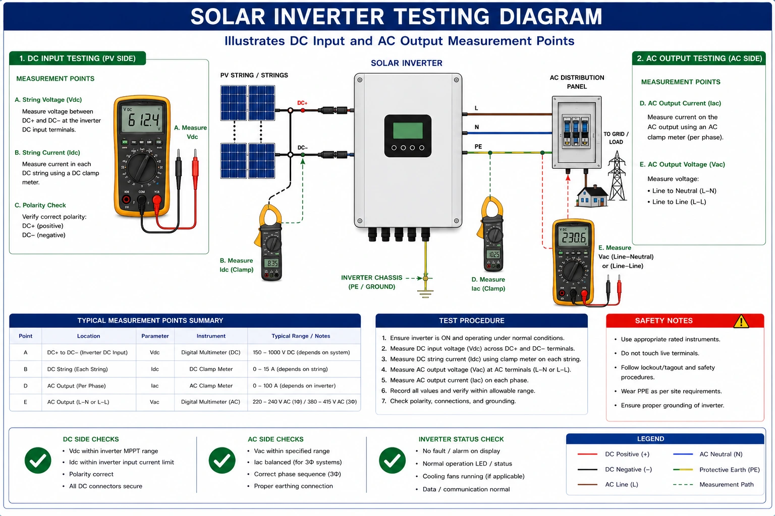
AC System Values That Must Be Measured
Several AC electrical parameters should be verified during commissioning.
1. AC Voltage
AC voltage indicates the electrical potential delivered by the inverter.
Measurements help verify:
- Grid compatibility
- Proper inverter operation
- Voltage regulation
2. AC Current
Current measurement confirms:
- Power delivery
- Load sharing
- System performance
3. AC Frequency
Frequency verification ensures proper synchronization with the utility grid.
Abnormal frequency may indicate:
- Grid issues
- Inverter malfunction
4. Power Output
Power measurements confirm actual energy production.
Comparisons should be made with:
- Design values
- Irradiance conditions
- Expected performance
5. Power Factor
Power factor indicates the efficiency of power utilization. Modern inverters often provide power factor control capabilities.
6. Energy Production
Energy output data helps verify:
- System performance
- Operational efficiency
- Renewable energy generation targets
Components Involved in Inverter Verification
Testing typically involves:
- Solar inverter
- AC combiner box
- Utility disconnect
- Distribution panel
- Monitoring system
- Utility interconnection point
Tools Required for Inverter Verification and AC Measurements
1. Digital Multimeter
Used for:
- Voltage measurements
- Continuity testing
- Preliminary inspections
2. Clamp Meter
Measures AC current safely without disconnecting conductors.
3. Power Analyzer
Provides detailed measurements including:
- Voltage
- Current
- Frequency
- Power factor
- Power output
4. Energy Meter
Measures energy generation and consumption.
5. Inverter Monitoring Interface
Used to review:
- Operational status
- Fault logs
- Performance data
6. Insulation Resistance Tester
May be used as part of commissioning verification procedures.
Pre-Commissioning Inspection Requirements
Before testing inverter operation:
- Verify Mechanical Installation
Check:
- Mounting security
- Ventilation clearances
- Environmental protection
Inspect Electrical Connections
Verify:
- DC connections
- AC wiring
- Grounding system
- Protection devices
Review Design Documentation
Examine:
- Single Line Diagram (SLD)
- Equipment datasheets
- Manufacturer manuals
Step-by-Step Procedure to Verify Inverter Operation
Step 1 – Confirm DC Input Availability
Verify that the solar array is producing appropriate DC voltage.
Measure:
- String voltage
- Array voltage
Ensure values are within inverter operating limits.
Step 2 – Energize the Inverter
Follow manufacturer startup procedures.
Observe:
- Display indicators
- Startup sequence
- Warning messages
Step 3 – Verify Grid Synchronization
Confirm that the inverter successfully synchronizes with the utility grid.
Check:
- Voltage matching
- Frequency matching
- Operational status indicators
Step 4 – Confirm Normal Operation
Verify:
- Power production
- AC output values
- Monitoring system status
The inverter should operate without alarms or fault messages.
Step 5 – Record Operational Data
Document:
- Voltage
- Current
- Frequency
- Power output
- Environmental conditions
Measuring AC Voltage
Use a calibrated multimeter or power analyzer.
Measure:
- Phase-to-phase voltage (where applicable)
- Phase-to-neutral voltage
Compare readings with design specifications.
Measuring AC Current
Use an AC clamp meter.
Measure:
- Individual phase currents
- Total output current
Verify balanced current distribution where applicable.
Measuring AC Frequency
Frequency is typically measured using:
- Power analyzers
- Multimeters with frequency functions
Verify compliance with utility requirements.
Measuring Power Output
Power measurements help determine:
- Inverter efficiency
- System performance
- Expected energy production
Compare values with irradiance and design calculations.
Measuring Power Factor
Power factor measurements verify:
- Efficient power utilization
- Utility compliance
- Inverter control settings
Step-by-Step Procedure for Anti-Islanding Verification
Step 1 – Review Utility Requirements
Verify applicable anti-islanding requirements and testing procedures.
Step 2 – Prepare the System
Ensure:
- Safe operating conditions
- Authorized personnel present
- Testing approvals obtained
Step 3 – Simulate Grid Loss
Disconnect the utility supply according to approved procedures.
Step 4 – Observe Inverter Response
Verify that:
- The inverter detects grid loss
- Power production stops
- AC output disconnects
Step 5 – Measure Disconnect Time
Record the time required for inverter shutdown. Verify compliance with applicable standards and manufacturer specifications.
Step 6 – Restore Grid Connection
Reconnect the utility supply.
Verify that the inverter:
- Re-synchronizes correctly
- Resumes normal operation
Typical Indicators of Proper Inverter Operation
Signs of correct operation include:
- Stable AC voltage
- Proper frequency synchronization
- Balanced phase currents
- Expected power output
- No active fault alarms
- Successful anti-islanding response
Common Issues Detected During Testing
Low AC Voltage
Possible causes:
- Grid issues
- Wiring problems
- Inverter faults
Low Power Output
Possible causes:
- Shading
- Module issues
- Incorrect settings
Grid Synchronization Failure
Possible causes:
- Frequency mismatch
- Voltage abnormalities
- Utility connection issues
Anti-Islanding Failure
Possible causes:
- Protection configuration errors
- Firmware issues
- Faulty equipment
Conclusion
Verifying inverter operation, measuring AC electrical parameters, and testing anti-islanding functionality are critical steps in the commissioning and maintenance of solar PV systems. These activities ensure that the inverter operates safely, synchronizes correctly with the utility grid, and delivers the expected energy output while complying with safety and grid-interconnection requirements.
Inverter commissioning and performance verification are essential components of successful solar electricity generation and renewable energy technology implementation. Furthermore, following recommendations and standards promoted by the Ministry of New and Renewable Energy helps ensure reliable, safe, and compliant solar PV installations.
By using calibrated testing equipment, following approved commissioning procedures, documenting all measurements, and verifying protection functions such as anti-islanding, solar installers and EPC professionals can optimize solar panel system cost, improve renewable solar system reliability, and ensure the long-term success of residential, commercial, industrial, and utility-scale solar projects.
FAQs
Q1. What is the purpose of inverter verification in a solar PV system?
Ans: Inverter verification ensures that the inverter operates correctly, converts DC power efficiently, synchronizes with the grid, and performs all required protection functions.
Q2. What is anti-islanding protection?
Ans: Anti-islanding protection prevents the inverter from supplying power to local loads when the utility grid is unavailable, ensuring personnel and equipment safety.
Q3. Which AC parameters should be measured during commissioning?
Ans: Key parameters include AC voltage, AC current, frequency, power output, power factor, and energy generation.
Q4. Why is anti-islanding testing mandatory?
Ans: It confirms compliance with utility requirements and verifies that the inverter disconnects safely during grid outages.
Q5. What tools are commonly used for AC system measurements?
Ans: Digital multimeters, clamp meters, power analyzers, energy meters, and inverter monitoring systems are commonly used.
Are Colleges and Schools ready to take up Solar challenge?
Adopting solar energy can help schools and colleges reduce electricity costs and promote sustainability. This guide explores how educational institutions can implement rooftop solar projects, the benefits, and what steps are needed to take on the solar challenge effectively.

India’s Renewable Energy Revolution: The Role of Agrivoltaics
Agrivoltaics, the integration of solar panels with agricultural land, is emerging as a key driver in India’s renewable energy revolution. This blog explains how agrivoltaics supports sustainable farming, increases land efficiency, and contributes to clean energy production, helping India meet its solar energy targets while boosting rural economies.
Solar Cable Termination: Tools, Steps & Best Practices
A complete guide to cable continuity testing in solar installations, including testing procedures, tools, and safety best practices.
Standalone Solar PV System Startup Guide
A complete guide to standalone solar PV system startup, including commissioning steps, safety inspections, and operational checks for reliable performance.
From Solar Design to Site: Locating Footings for Solar Mounting Structures
A complete guide to translating solar design drawings into accurate footing locations on-site, including survey methods, marking techniques, and EPC best practices.

Solar Microgrid Solutions: Smart, Reliable & Scalable Power Systems
Solar microgrid solutions provide smart, reliable, and scalable power by integrating solar energy, battery storage, and intelligent control systems. These systems ensure uninterrupted electricity for industries, campuses, communities, and remote locations while reducing grid dependency and energy costs.
How to Perform Cable Continuity Tests in Solar PV Systems
A complete guide to cable continuity testing for solar PV systems, ensuring safe, reliable, and properly connected electrical installations.
Solar PV Maximum Working Voltage: Limits & Design Guide
A complete guide to maximum working voltage in solar PV systems, covering limits, calculations, and key design considerations.