Solar photovoltaic (PV) inverters are among the most sophisticated components of a solar power system. They convert the direct current (DC) generated by solar modules into alternating current (AC), synchronize with the utility grid, manage safety functions, communicate with monitoring systems, and optimize overall energy production. Modern inverters contain complex electronic assemblies, including printed circuit boards (PCBs), power semiconductor devices, microprocessors, communication modules, sensors, relays, capacitors, transformers (where applicable), and protective circuitry.
While many inverter issues can be resolved through routine maintenance—such as tightening electrical connections, replacing fuses, updating firmware, or correcting wiring faults—circuit board-level faults require specialized diagnosis and repair. These faults often involve damaged electronic components, burnt tracks, failed integrated circuits (ICs), communication boards, gate drivers, or power control boards. Attempting to repair such faults without proper authorization, specialized tools, or technical expertise can cause additional damage, compromise warranty coverage, create electrical hazards, and increase system downtime.
Therefore, when routine troubleshooting confirms a circuit board-level fault, field technicians should stop further internal repair attempts, document all observations, and promptly inform the authorized inverter service technician or manufacturer’s service center. Escalating complex electronic faults ensures that repairs are carried out safely, professionally, and in accordance with manufacturer specifications.
Recognizing the limits of field-level maintenance and referring advanced electronic repairs to qualified service personnel is an essential responsibility for solar installers, commissioning engineers, EPC contractors, and operations and maintenance (O&M) professionals.
This comprehensive guide explains circuit board-level faults, common symptoms, inspection procedures, reporting methods, documentation practices, safety precautions, and industry best practices.
Why Is the Solar Inverter Important?
The inverter performs several essential functions:
- Converts DC to AC power.
- Synchronizes with the electrical grid.
- Monitors system performance.
- Protects against electrical faults.
- Supports anti-islanding protection.
- Communicates with monitoring platforms.
- Maximizes solar electricity production.
A malfunctioning inverter can significantly reduce overall system performance.
What Is a Circuit Board Level Fault?
A circuit board level fault is an internal electronic failure affecting one or more printed circuit boards (PCBs) inside the inverter.
Examples include:
- Burnt electronic components
- Failed Integrated Circuits (ICs)
- Damaged communication boards
- Burnt PCB tracks
- Failed gate driver circuits
- Capacitor failure
- Power semiconductor failure
- Processor malfunction
- Sensor failure
- Relay driver failure
These faults generally require specialized equipment and manufacturer-approved repair procedures.
Why Should Field Technicians Not Repair Circuit Boards?
Unauthorized repairs may:
- Void manufacturer warranty
- Damage additional components
- Compromise electrical safety
- Affect inverter calibration
- Reduce long-term reliability
- Cause repeated failures
Only trained and authorized service technicians should perform PCB-level repairs.
Common Symptoms of Circuit Board Level Faults
Technicians may observe:
- Inverter fails to start
- Blank display
- Persistent fault codes
- Communication failure
- Continuous restart cycles
- Burning smell
- Visible smoke damage
- Burnt electronic components
- Unusual noises
- Failed self-diagnostics
- Power conversion failure
These symptoms require further investigation.
Possible Causes of PCB Failure
Common causes include:
- Lightning surges
- Voltage spikes
- Component aging
- Moisture ingress
- Manufacturing defects
- Excessive heat
- Cooling fan failure
- Dust accumulation
- Power semiconductor failure
- Incorrect installation
- Short circuits
Preventive maintenance helps reduce these risks.
Tools Required for Preliminary Inspection
Field technicians commonly use:
- Digital multimeter
- Clamp meter
- Insulation resistance tester
- Infrared thermal camera
- Laptop with inverter monitoring software
- Inspection flashlight
- Screwdriver set (where authorized)
- Personal Protective Equipment (PPE)
Component-level electronic repair equipment should only be used by authorized service personnel.
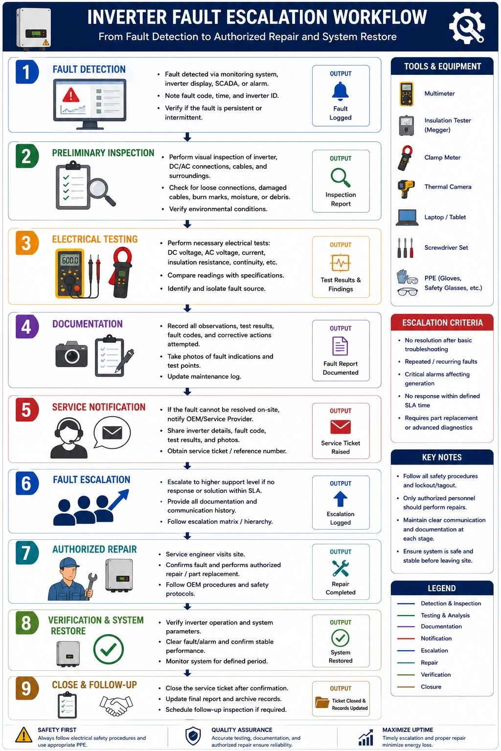
Step-by-Step Procedure
Step 1 – Ensure Safety
Before inspection:
- Follow Lockout/Tagout (LOTO) procedures where applicable.
- Isolate DC and AC supplies if required.
- Verify the work area is safe.
- Wear appropriate PPE.
Safety is always the highest priority.
Step 2 – Review Inverter Status
Check:
- Display messages
- LED indicators
- Audible alarms
- Event logs
- Monitoring software
Record all fault indications before taking further action.
Step 3 – Inspect External Components
Inspect:
- DC cables
- AC cables
- Connectors
- Fuses
- Circuit breakers
- Cooling fans
- Air filters
- Ventilation openings
External faults should be eliminated before suspecting PCB failure.
Step 4 – Verify Electrical Parameters
Measure:
- DC input voltage
- AC output voltage
- Grid frequency
- String current
Confirm that electrical inputs are within normal operating limits.
Step 5 – Perform Visual Inspection
Where permitted by the manufacturer and only after safely isolating the equipment, inspect for:
- Burn marks
- Swollen capacitors
- Damaged connectors
- Moisture
- Dust accumulation
- Corrosion
Do not attempt component-level repairs.
Step 6 – Review Fault Codes
Compare inverter error codes with:
- Manufacturer manuals
- Service documentation
- Technical bulletins
Some fault codes specifically indicate internal PCB failures.
Step 7 – Confirm Circuit Board Level Fault
If troubleshooting confirms:
- Internal electronic failure
- Failed PCB
- Burnt components
- Persistent internal fault
Stop further repair attempts.
Do not remove or replace electronic components unless specifically authorized.
Step 8 – Document Findings
Record:
- Fault codes
- Operating conditions
- Voltage measurements
- Current measurements
- Visual observations
- Environmental conditions
- Photographs (if permitted)
Accurate documentation assists the service technician.
Step 9 – Inform the Authorized Inverter Service Technician
Provide:
- Site details
- Inverter model
- Serial number
- Commissioning date
- Fault codes
- Inspection report
- Test results
- Maintenance history
- Photographs
Clear communication reduces repair time.
Step 10 – Follow Manufacturer Instructions
After reporting:
- Await technical guidance.
- Do not restart the inverter unless instructed.
- Follow all manufacturer recommendations.
Only authorized personnel should replace circuit boards.
Information to Include in the Service Report
The report should include:
- Site name
- Customer details
- Date
- Inverter make and model
- Serial number
- Firmware version
- Fault codes
- Measured voltages
- Measured currents
- Ambient temperature
- Inspection findings
- Corrective actions already performed
- Technician details
Proper documentation supports efficient repairs.
Benefits of Timely Escalation
Improved Renewable Solar System Reliability
Professional repairs restore system performance.
Increased Solar Electricity Generation
Quick repairs reduce downtime.
Enhanced Safety
Avoids unsafe field repairs.
Protection of Manufacturer Warranty
Authorized repairs help maintain warranty coverage.
Lower Long-Term Maintenance Costs
Proper diagnosis prevents repeated failures and unnecessary component replacement.
Conclusion
Recognizing and reporting circuit board-level faults is an essential responsibility for professionals involved in the installation, commissioning, and maintenance of solar PV systems. While many inverter issues can be resolved through routine inspection and electrical testing, internal PCB failures require specialized knowledge, manufacturer-approved procedures, and dedicated diagnostic equipment. By performing systematic preliminary inspections, verifying electrical parameters, reviewing fault codes, documenting observations thoroughly, and promptly informing the authorized inverter service technician, field personnel can ensure that repairs are carried out safely and effectively without compromising equipment integrity or warranty coverage.
Understanding the limits of field-level maintenance and escalating advanced electronic faults appropriately is a key competency for solar installers, EPC contractors, commissioning engineers, and operations and maintenance professionals. Furthermore, following technical recommendations and safety practices promoted by the Ministry of New and Renewable Energy, together with manufacturer guidelines and local electrical standards, ensures that inverter faults are managed professionally and in compliance with industry requirements.
By maintaining detailed service records, using calibrated testing instruments, avoiding unauthorized repairs, communicating effectively with manufacturer-approved service technicians, and addressing inverter faults promptly, solar professionals can optimize solar panel system cost, improve renewable solar system reliability, maximize solar electricity generation, reduce the cost of solar per kWh installed, and ensure the long-term success of residential, commercial, industrial, and utility-scale solar energy projects.
FAQs
Q1. What is a circuit board level fault in a solar inverter?
Ans: A circuit board-level fault is an internal electronic failure affecting one or more printed circuit boards (PCBs), such as the control board, communication board, or power electronics board. These faults generally require specialized diagnostic equipment and manufacturer-approved repair procedures.
Q2. Should a field technician repair a damaged inverter circuit board?
Ans: No. Field technicians should not attempt PCB-level repairs unless they are specifically trained and authorized by the inverter manufacturer. Unauthorized repairs may create safety hazards, damage the inverter further, and void the manufacturer’s warranty.
Q3. What information should be provided to the inverter service technician?
Ans: The report should include the inverter model, serial number, fault codes, voltage and current measurements, inspection observations, maintenance history, photographs (if permitted), and any corrective actions already performed.
Q4. What are the common signs of a circuit board-level fault?
Ans: Typical signs include a blank display, repeated fault codes, communication failure, continuous restart cycles, burning smell, visible damage to electronic components, and failure to produce AC output despite normal DC input conditions.
Q5. Why is documenting inverter faults important?
Ans: Accurate documentation helps the authorized service technician diagnose the issue more efficiently, reduces repair time, supports warranty claims, and creates a maintenance history that can be used for future troubleshooting.

Solar Savings Made Simple: Know Your Cost Cuts in 2025
Maximize your solar savings in 2025. Learn how solar energy reduces electricity costs for homes and businesses.
Solar PV Procurement Process Guide for EPC & Installers | Step-by-Step
A well-planned procurement process is critical for the success of any solar PV project. This guide explains step-by-step how EPC companies and installers can efficiently source solar panels, inverters, and balance of system components while ensuring quality, cost-effectiveness, and timely delivery.
Earthing & Lightning Protection Testing for Solar PV Systems
A complete guide to earthing and lightning protection testing for solar PV systems, ensuring safety, regulatory compliance, and long-term system reliability.
1 MW Solar Plant Cost in Haryana | A Complete Guide
Planning a 1 MW solar power plant in Haryana? This guide covers complete 2025 cost details, subsidy schemes, ROI, and savings potential for industrial users.
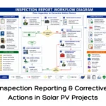
Inspection Reporting and Corrective Actions
A complete guide to preparing solar PV inspection reports and implementing corrective actions to ensure quality, compliance, and project performance.
Solar String Sizing Check: Did Your Installer Get It Right?
Worried your rooftop solar strings might be sized incorrectly? Check these tips to ensure your Solar PV system is installed for maximum efficiency and safety
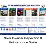
Solar Inverter Inspection & Maintenance Guide
A complete guide to solar inverter inspection and maintenance, including visual inspections, performance checks, fault diagnosis, cleaning, and preventive maintenance to maximize efficiency and reliability.
Solar Roof Hook Installation: Step-by-Step Guide
A step-by-step guide to solar roof hook installation, covering positioning, alignment, and best practices for strong and reliable rooftop systems.