In solar photovoltaic (PV) systems, grounding is one of the most critical safety measures for protecting personnel, equipment, and property from electrical faults, lightning strikes, and surge currents. While installers often focus on solar panels, inverters, and mounting structures, the grounding system plays an equally important role in ensuring safe and reliable solar electricity generation.
A properly sized grounding conductor provides a low-resistance path for fault currents and helps prevent electric shock, equipment damage, and fire hazards. Conversely, an undersized grounding conductor may fail to carry fault current safely, leading to dangerous operating conditions and increased solar installation charges due to repairs and system downtime.
Grounding and earthing are fundamental aspects of renewable solar projects and electrical safety practices.
This blog provides a complete guide to determining grounding conductor size for solar PV systems, including sizing factors, calculation methods, applicable standards, installation considerations, and best practices for installers and EPC professionals.
What is a Grounding Conductor?
A grounding conductor is a conductor used to connect electrical equipment, solar mounting structures, modules, inverters, and other metallic parts to the grounding system.
Its primary functions include:
- Providing a path for fault current
- Reducing electric shock risk
- Protecting equipment from surges
- Supporting lightning protection systems
- Maintaining system safety during abnormal conditions
Grounding conductors are commonly installed throughout renewable solar systems, including rooftop, commercial, industrial, and utility-scale solar plants.
Importance of Proper Grounding Conductor Sizing
Correct grounding conductor sizing helps:
- Improve personnel safety
- Protect solar equipment
- Reduce fire risks
- Improve fault-clearing performance
- Enhance lightning protection
- Optimize solar panel system cost
Improper sizing can result in:
- Overheating conductors
- Fault current damage
- Increased maintenance costs
- Solar installation cost per kWh increases due to system failures
Types of Grounding Conductors in Solar PV Systems
1. Equipment Grounding Conductor (EGC)
Used to connect:
- Solar module frames
- Mounting structures
- Inverters
- Combiner boxes
Purpose:
- Equipment fault protection
2. Grounding Electrode Conductor (GEC)
Connects the grounding system to:
- Ground rods
- Earth electrodes
- Ground grids
Purpose:
- Establishes earth connection
3. Lightning Protection Grounding Conductor
Used in systems equipped with lightning protection.
Purpose:
- Safely dissipates lightning currents
Why Grounding is Essential in Solar PV Systems
Solar installations are exposed to:
- Outdoor weather conditions
- Lightning activity
- High DC voltages
- Electrical faults
Grounding provides:
- Safe fault current paths
- Voltage stabilization
- Improved equipment protection
This is particularly important for large renewable energy technology projects.
Factors Affecting Grounding Conductor Size
Several factors influence grounding conductor sizing.
1. System Voltage
Higher system voltages may require larger grounding conductors.
Common solar system voltages include:
- 600 V DC
- 1000 V DC
- 1500 V DC
2. Fault Current Magnitude
The grounding conductor must safely carry anticipated fault currents without damage. Higher fault current levels require larger conductor sizes.
3. Protective Device Rating
Grounding conductor size is often related to:
- Circuit breaker ratings
- Fuse ratings
- Disconnect switch ratings
4. Conductor Material
Grounding conductors are commonly manufactured from:
Copper
Benefits:
- High conductivity
- Corrosion resistance
- Long lifespan
Aluminum
Benefits:
- Lower cost
- Lightweight
However, aluminum requires larger cross-sectional areas than copper.
5. Installation Environment
Consider:
- Soil conditions
- Corrosion exposure
- Temperature
- Moisture levels

Common Grounding Conductor Materials
Material | Advantages |
Copper | High conductivity, corrosion-resistant |
Tinned Copper | Enhanced corrosion protection |
Aluminum | Lightweight and economical |
Copper-Clad Steel | Strong mechanical performance |
Copper remains the most commonly used grounding conductor material in solar PV systems.
General Grounding Conductor Sizing Principles
Grounding conductors should be sized according to:
- Electrical standards
- Fault current calculations
- Equipment ratings
- Local regulations
The conductor must be capable of carrying fault current safely until protective devices operate.
Typical Grounding Conductor Sizes Used in Solar PV Systems
Application | Common Copper Size |
Module Frame Bonding | 4 mm² to 6 mm² |
Structure Grounding | 6 mm² to 16 mm² |
Inverter Grounding | 6 mm² to 16 mm² |
Grounding Electrode Connection | 16 mm² to 35 mm² |
Utility-Scale Ground Grid | 35 mm² and above |
Actual sizing should always be determined through engineering calculations and applicable standards.
Step-by-Step Process to Determine Grounding Conductor Size
Step 1 – Review System Design Documents
Study:
- Single Line Diagram (SLD)
- Earthing layout drawings
- Electrical specifications
Identify:
- System voltage
- Equipment ratings
- Grounding requirements
Step 2 – Determine Fault Current Levels
Calculate or obtain:
- Maximum fault current
- Short-circuit current ratings
This information is typically available from:
- Inverter datasheets
- Electrical design calculations
Step 3 – Identify Protective Device Ratings
Review:
- Fuse ratings
- Circuit breaker ratings
- Disconnect devices
Grounding conductor sizing is often coordinated with these protection devices.
Step 4 – Select Grounding Conductor Material
Choose:
- Copper
- Tinned copper
- Aluminum
Based on:
- Environmental conditions
- Project budget
- Regulatory requirements
Step 5 – Apply Applicable Standards
Follow the grounding requirements specified by:
- National electrical regulations
- Utility interconnection requirements
- Solar project design standards
Installers should comply with guidelines from the Ministry of New and Renewable Energy wherever applicable.
Step 6 – Verify Mechanical Strength
The conductor should withstand:
- Installation stress
- Environmental exposure
- Long-term operation
Grounding Requirements for Solar Components
Solar Module Frames
Require equipment grounding to:
- Eliminate touch voltage hazards
- Ensure fault protection
Mounting Structures
Grounding protects metallic structures from:
- Fault currents
- Lightning effects
Solar Inverters
Proper inverter grounding:
- Improves operational safety
- Supports surge protection
Combiner Boxes
Require grounding of:
- Enclosures
- Internal equipment
Battery Banks
Hybrid and off-grid systems require:
- Battery grounding
- Equipment bonding
Conclusion
Determining the correct grounding conductor size is essential for ensuring the safety, reliability, and compliance of solar PV systems. Properly sized grounding conductors protect personnel, equipment, and infrastructure from electrical faults, surge currents, and lightning-related risks.
Grounding forms a fundamental part of renewable solar systems and safe solar electricity generation. Additionally, following recommendations and guidelines established by the Ministry of New and Renewable Energy helps ensure standardized and compliant installations.
By applying correct grounding conductor sizing principles, performing proper testing, and following industry best practices, solar professionals can optimize solar panel system cost, improve system performance, and support the long-term success of renewable energy technology projects across residential, commercial, industrial, and utility-scale applications.
FAQs
Q1. Why is grounding conductor sizing important in solar PV systems?
Ans: Proper sizing ensures fault currents can be carried safely without damaging the conductor or connected equipment.
Q2. What factors affect grounding conductor size?
Ans: Key factors include fault current levels, system voltage, protective device ratings, conductor material, and applicable standards.
Q3. Which material is commonly used for grounding conductors in solar projects?
Ans: Copper is the most widely used material because of its high conductivity and corrosion resistance.
Q4. Does grounding conductor sizing affect solar panel system cost?
Ans: Yes. Proper sizing reduces maintenance, equipment damage, and downtime, helping optimize overall system costs.
Q5. How can installers verify grounding conductor performance after installation?
Ans: Through grounding continuity testing, ground resistance testing, visual inspections, and documentation review.
Role of PV Solar Installer in India – Responsibilities, Skills, and Industry Importance
PV solar installers play a critical role in India’s rapidly expanding solar energy sector. From rooftop systems to large-scale industrial projects, skilled installers ensure safe, efficient, and compliant solar plant deployment. This guide explains the responsibilities, technical skills, certifications, and career opportunities for PV solar installers in India, along with their growing importance in supporting the nation’s renewable energy transition.
MPPT and PWM: Which Solar Charge Controller Is Better?
MPPT and PWM are the two most common solar charge controllers. This guide explains MPPT and PWM differences, efficiency, cost, and usage.
Industrial Solar Power: 7 Reasons to Make the Switch
Top 7 benefits of solar energy for industries, including cost savings, environmental impact, and improved energy reliability.
India and Japan Strengthen Renewable Energy Cooperation
India and Japan have initiated a partnership under the Asia Energy Transition Initiative (AETI) to support India’s clean energy transition. India has set an ambitious target of achieving net-zero by 2070, while Japan aims to achieve the same by 2050.
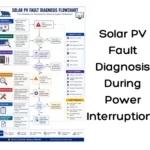
Solar PV Fault Diagnosis During Power Interruptions
A complete guide to identifying faults in solar PV systems during power generation interruptions, including troubleshooting techniques, root cause analysis, and corrective maintenance.
Solar Power System Efficiency: How to Calculate for Residential, Industrial & Commercial Use
Understand and measure your solar system’s performance. Maximize energy output at home, industrial units, and commercial buildings
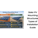
Solar PV Mounting Structures: Types & Installation Guide
A complete guide to solar mounting structures types in PV systems, covering fixed tilt, tracking, and rooftop installations for installers.
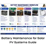
Battery Maintenance for Solar PV Systems Guide
A complete guide to battery maintenance for solar PV systems, including inspection, cleaning, testing, charging, and preventive maintenance to ensure long battery life and reliable performance.