Solar photovoltaic (PV) systems consist of multiple solar modules connected in series to form a string. Since all modules in a series string carry the same current, the performance of the entire string depends on the condition of every individual module. If one module becomes defective due to manufacturing defects, physical damage, hotspot formation, cracked cells, bypass diode failure, moisture ingress, or aging, the overall current and power output of the string may decrease significantly.
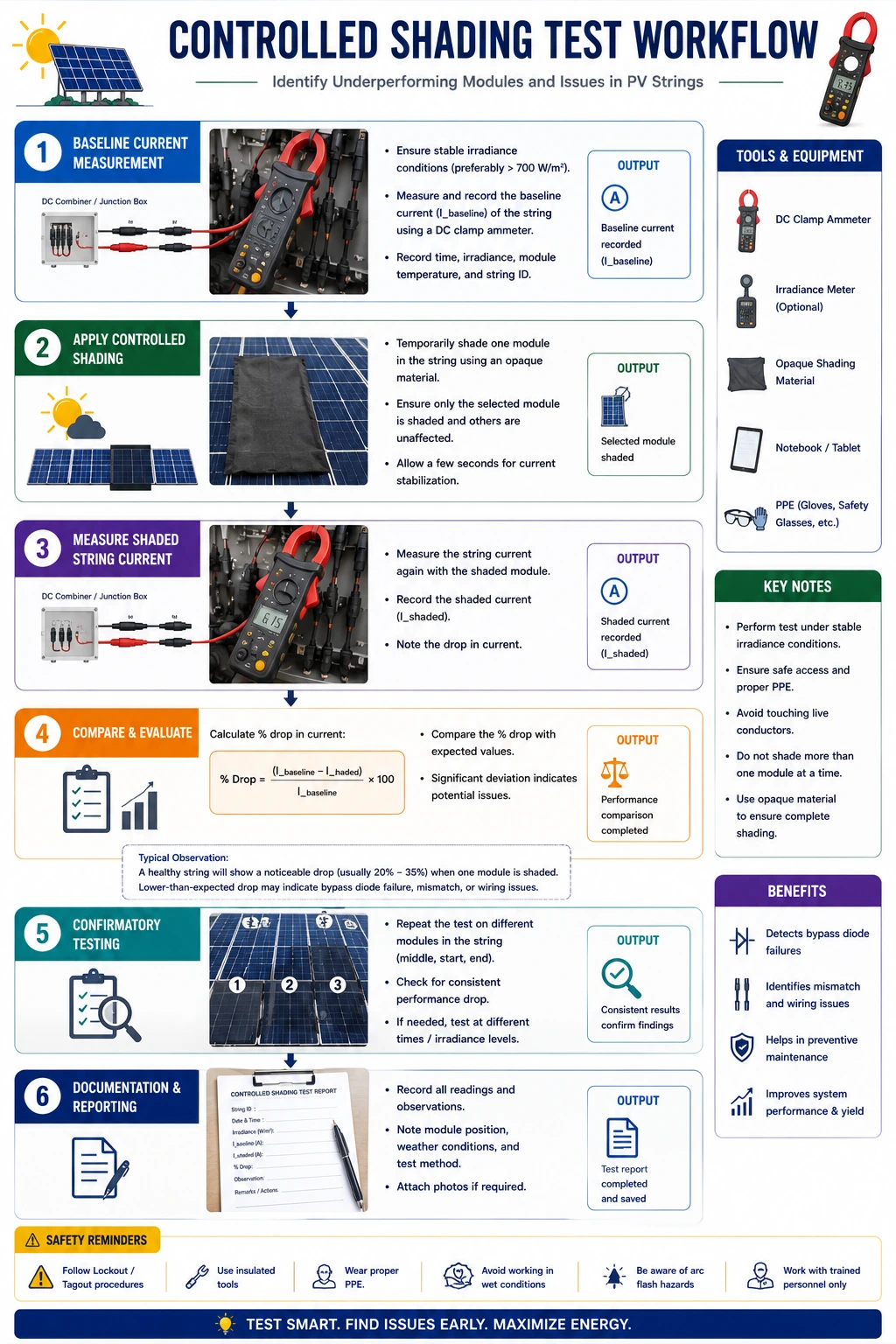
One of the practical field techniques used by solar technicians during maintenance and troubleshooting is the controlled shading method combined with ammeter (DC clamp meter) current measurements. This method helps identify a faulty module within a string by observing how the string current changes when each module is temporarily shaded. A healthy module will normally produce a noticeable reduction in string current when shaded, while a faulty or already underperforming module may show little or no change in the measured current.
This diagnostic technique is especially useful when monitoring data indicates reduced string performance but visual inspection alone cannot identify the defective module. It should always be performed carefully under controlled conditions and in accordance with manufacturer recommendations and electrical safety procedures.
Identifying faulty modules through systematic testing and electrical measurements is an important troubleshooting skill for solar installers, commissioning engineers, EPC contractors, and operations and maintenance (O&M) professionals.
This comprehensive guide explains the principles behind the shading method, testing procedures, required tools, safety precautions, interpretation of ammeter readings, documentation requirements, and industry best practices.
Why Is It Important to Identify Faulty Modules?
A single defective module can reduce the output of an entire string.
Early identification helps to:
- Restore normal power generation
- Improve the renewable solar system efficiency
- Reduce energy losses
- Prevent hotspot damage
- Extend the module lifespan
- Reduce maintenance costs
- Improve overall solar electricity production
Prompt troubleshooting minimizes downtime and improves system reliability.
Understanding Solar PV Strings
A PV string consists of multiple modules connected in series.
In a series circuit:
- Voltage is added across all modules.
- The same current flows through every module.
If one module performs poorly, the current of the entire string may be limited.
Principle of the Controlled Shading Method
A healthy solar module contributes to the current produced by the string.
When a healthy module is temporarily shaded:
- The available sunlight decreases.
- The module produces less current.
- The measured string current decreases noticeably.
If shading a module produces little or no change in string current, it may indicate that the module is already underperforming or faulty.
Note: This is a field troubleshooting technique used for diagnostic purposes only. It should be performed carefully, temporarily, and alongside other electrical tests such as voltage measurements, thermal imaging, insulation resistance testing, and IV curve analysis before concluding that a module is defective.
Common Causes of Faulty Modules
Faulty modules may result from:
- Cracked solar cells
- Delamination
- Hotspots
- Moisture ingress
- Glass breakage
- Burn marks
- Bypass diode failure
- Internal solder joint failure
- Manufacturing defects
- Long-term degradation
Routine inspections help identify these issues early.
When Should This Test Be Performed?
The controlled shading method is useful when:
- One string generates a lower current than the others.
- Monitoring software indicates reduced performance.
- Visual inspection does not reveal obvious damage.
- Thermal imaging suggests abnormal temperatures.
- IV curve analysis indicates possible module degradation.
It should not replace comprehensive diagnostic testing but should complement it.
Tools Required
Technicians commonly use:
- DC clamp meter (preferred) or calibrated DC ammeter
- Digital multimeter
- Infrared thermal camera
- IV curve tracer
- Irradiance meter (Pyranometer)
- Module layout drawing
- Inspection checklist
- Personal Protective Equipment (PPE)
Only calibrated instruments should be used for accurate measurements.
Step-by-Step Procedure
Step 1 – Review System Documentation
Before testing:
Review:
- String layout
- Electrical drawings
- Module datasheets
- Previous maintenance records
Understand the expected operating current.
Step 2 – Verify Environmental Conditions
Record:
- Solar irradiance
- Ambient temperature
- Module temperature
Testing should be carried out under stable sunlight to obtain reliable results.
Step 3 – Perform Visual Inspection
Inspect modules for:
- Cracks
- Dust
- Bird droppings
- Delamination
- Burn marks
- Loose connectors
- Broken cables
Correct visible issues before electrical testing.
Step 4 – Measure Baseline String Current
Using a DC clamp meter:
- Measure and record the operating current of the string before any module is shaded.
This serves as the reference value.
Step 5 – Shade One Module at a Time
- Temporarily cover one module using a suitable opaque sheet designed for testing or another safe, non-damaging covering method.
- Avoid scratching or placing excessive weight on the module.
- Observe the ammeter reading while the module is shaded.
- Remove the cover before moving to the next module.
Step 6 – Record Ammeter Readings
For each module, record:
- Module identification
- Baseline current
- Current while shaded
- Difference in current
- Observations
Maintain consistent irradiance during testing.
Step 7 – Compare Results
- Healthy modules generally produce a noticeable decrease in string current when shaded.
- If shading a module results in significantly less change than expected compared with other modules tested under similar conditions, that module may require further investigation.
- The result should always be confirmed using additional diagnostic methods.
Step 8 – Perform Confirmatory Tests
After identifying a suspected module:
Perform:
- Open Circuit Voltage (Voc)
- Short Circuit Current (Isc)
- Thermal imaging
- IV curve testing
- Visual inspection
- Connector inspection
- Insulation resistance testing
Confirm the fault before replacing the module.
Step 9 – Carry Out Corrective Actions
Depending on the confirmed fault:
- Clean the module
- Repair connectors
- Replace damaged cables
- Replace defective bypass diodes (where serviceable)
- Replace the faulty module if necessary
Always verify performance after repairs.
Step 10 – Prepare the Inspection Report
Document:
- Test conditions
- Ammeter readings
- Irradiance
- Suspected module
- Confirmatory test results
- Corrective actions
- Technician details
Maintain complete maintenance records.
Interpretation of Ammeter Readings
Examples:
Observation | Possible Interpretation |
Noticeable drop in current when the module is shaded | The module is likely contributing normally to the string output |
Very small or no change in current when the module is shaded | The module may already be underperforming or faulty; confirm with additional tests |
Current fluctuates during testing | Loose connection or unstable environmental conditions |
The entire string shows very low current | Multiple faults, inverter issue, shading, or low irradiance |
Results should always be interpreted alongside irradiance, temperature, and other diagnostic measurements.
Conclusion
Identifying faulty modules within a solar PV string is essential for maintaining maximum system efficiency and reliable solar electricity generation. The controlled shading method, combined with ammeter or DC clamp meter readings, provides technicians with a practical field technique for identifying modules that may be underperforming. However, because environmental conditions and system characteristics can influence measurements, the results should always be verified using additional diagnostic methods such as thermal imaging, IV curve testing, voltage measurements, insulation resistance testing, and detailed visual inspections before any replacement decisions are made.
Systematic fault diagnosis is a key competency for solar installers, EPC contractors, commissioning engineers, and operations and maintenance professionals. Furthermore, following technical recommendations and safety practices promoted by the Ministry of New and Renewable Energy, together with manufacturer guidelines, helps ensure safe, standards-compliant, and accurate troubleshooting of renewable solar systems.
By implementing scheduled performance testing, using calibrated measuring instruments, maintaining detailed inspection records, confirming suspected faults with multiple diagnostic methods, and carrying out timely corrective actions, solar professionals can optimize solar panel system cost, improve renewable solar system reliability, maximize solar electricity generation, reduce the cost of solar per kWh installed, and ensure the long-term success of residential, commercial, industrial, and utility-scale solar energy projects.
FAQs
Q1. Why is the controlled shading method used in solar PV troubleshooting?
Ans: The controlled shading method helps technicians identify modules that may not be contributing normally to string current. It is a practical diagnostic technique that can highlight suspected faulty modules for further investigation.
Q2. What instrument is used to measure string current during this test?
Ans: A calibrated DC clamp meter is the preferred instrument because it measures current safely without disconnecting the circuit. A suitable DC ammeter may also be used where appropriate.
Q3. Does a small change in current always confirm that a module is faulty?
Ans: No. A small change in current indicates that the module may be underperforming, but additional tests, such as thermal imaging, IV curve analysis, voltage measurements, and visual inspection, should always be performed before confirming a fault or replacing the module.
Q4. Under what conditions should this test be performed?
Ans: Testing should be carried out during stable sunlight with minimal cloud cover. Solar irradiance, module temperature, and environmental conditions should be recorded to ensure an accurate comparison between modules.
Q5. What are the common reasons for low module performance?
Ans: Common causes include dust accumulation, partial shading, cracked cells, bypass diode failure, loose connectors, cable faults, delamination, moisture ingress, manufacturing defects, and natural module degradation.
PV System Maintenance Tools & Equipment Guide
A complete guide to performing the solar PV anti-islanding test, ensuring safe grid-connected operation, regulatory compliance, and reliable inverter performance.
China’s Solar Industry Poised for Continued Growth in 2023 and Beyond
China’s solar industry is set for continued growth in 2023 and beyond, driving global renewable energy expansion and technological advancements.
7 Common Myths about Solar Energy in India
Solar power is not only less expensive, but it is also the most abundant source of clean energy.

Researchers Propose New Way to Make Nuclear Power Plants Safer
Researchers propose innovative methods to enhance the safety of nuclear power plants, aiming to reduce risks and improve operational security.
How Solar Energy Generation Is Calculated: A Simple Step-by-Step Guide
Understanding how solar energy generation is calculated helps estimate system output, savings, and ROI. This step-by-step guide explains the formula, key factors, and real-world examples to make solar energy calculation simple and practical.
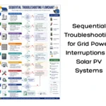
Sequential Troubleshooting for Grid Power Interruptions in Solar PV Systems
A complete guide to sequential troubleshooting in solar PV systems, helping identify and resolve faults during grid power supply interruptions through systematic testing and diagnosis.
Different Technical Parameters and Performance of a Solar PV Module
Earthing and lightning protection are critical safety components in solar PV installations. This guide explains their importance, types, components, and best practices for solar installers.
UP Discoms Propose 9.21% Electricity Tariff Hike for 2015-16
Uttar Pradesh Discoms propose a 9.21% increase in electricity tariffs for 2015-16, impacting residential, commercial, and industrial consumers across the state.