Solar photovoltaic (PV) systems are exposed to a wide range of environmental and electrical hazards throughout their operational life. Among the most critical protective systems in any solar installation are the earthing system and the lightning protection system (LPS). These systems are designed to safeguard personnel, equipment, and infrastructure from electrical faults, leakage currents, surge voltages, and lightning strikes.
However, simply installing grounding conductors, earth electrodes, and lightning protection components is not enough. Proper testing and verification must be performed to ensure these systems function as intended. Earthing and lightning protection tests help verify electrical continuity, grounding effectiveness, fault current dissipation capability, and overall compliance with design specifications and safety standards.
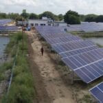
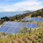
Whether the project is a residential rooftop solar installation, commercial solar power system, industrial solar plant, or utility-scale renewable solar project, testing earthing and lightning protection systems is an essential part of commissioning, periodic maintenance, troubleshooting, and regulatory compliance.
Failure to properly test these systems can lead to equipment damage, inverter failures, fire hazards, safety risks, production losses, and increased solar panel system cost throughout the life of the project.
Grounding and lightning protection verification are critical safety requirements for solar electricity generation and renewable energy technology deployment.
This comprehensive guide explains earthing and lightning protection testing procedures, required instruments, acceptance criteria, documentation requirements, safety precautions, and industry best practices.
Understanding Earthing in Solar PV Systems
Earthing, also known as grounding, is the process of connecting electrical equipment and conductive structures to the earth through a low-resistance path.
The purpose of earthing is to:
- Protect personnel from electric shock
- Safely dissipate fault currents
- Protect equipment from electrical faults
- Stabilize system voltages
- Improve operational safety
A properly designed grounding system is essential for every solar installation.
Understanding Lightning Protection Systems (LPS)
A lightning protection system is designed to intercept, conduct, and safely dissipate lightning energy into the ground.
The system typically includes:
- Air terminals (lightning rods)
- Down conductors
- Grounding electrodes
- Bonding conductors
- Surge protection devices (SPDs)
Lightning protection minimizes damage caused by direct and indirect lightning strikes.
Why Earthing and Lightning Protection Testing is Important
Testing ensures that:
- Grounding systems meet design requirements
- Earth resistance remains within acceptable limits
- Equipment bonding is effective
- Lightning protection systems function correctly
- Safety risks are minimized
Regular testing helps identify deterioration before it becomes a serious problem.
Objectives of Earthing and Lightning Protection Testing
The primary objectives include:
Safety Verification
- Ensuring protection against electrical shock and lightning hazards.
Equipment Protection
- Preventing damage to solar modules, inverters, batteries, and monitoring systems.
Regulatory Compliance
- Meeting project specifications and safety standards.
System Reliability
- Supporting uninterrupted renewable solar system operation.
Maintenance Planning
- Identifying degradation requiring corrective action.
Components That Require Testing
Several components should be included in earthing and lightning protection inspections.
1. Grounding Electrodes
Includes:
- Ground rods
- Earth pits
- Ground plates
These components provide the connection to Earth.
2. Grounding Conductors
Connect:
- Solar modules
- Mounting structures
- Inverters
- Combiner boxes
- Electrical equipment
3. Bonding Connections
Ensure electrical continuity between conductive parts.
4. Lightning Air Terminals
Designed to intercept lightning strikes.
5. Down Conductors
Carry lightning current safely to ground.
6. Surge Protection Devices (SPDs)
Protect electrical equipment from surge voltages.
Types of Earthing Tests
Several tests are performed to evaluate the grounding system performance.
1. Earth Resistance Test
Measures resistance between the grounding system and earth. This is the most important grounding test.
2. Ground Continuity Test
Verifies electrical continuity of grounding conductors.
3. Bonding Verification Test
Confirms electrical connections between conductive components.
4. Soil Resistivity Test
Evaluates soil characteristics affecting grounding performance. Often performed during project design and expansion activities.
Types of Lightning Protection Tests
Testing may include:
Visual Inspection
- Verifying the physical condition of components.
Continuity Testing
- Confirming electrical continuity throughout the system.
Ground Resistance Testing
- Verifying effective lightning current dissipation.
SPD Verification
- Checking the surge protection device condition and operation.
Tools Required for Earthing and Lightning Protection Testing
1. Earth Resistance Tester
Also called an earth ground tester.
Used to measure:
- Ground resistance
- Grounding effectiveness
2. Digital Multimeter
Used for continuity and electrical verification.
3. Clamp Ground Resistance Tester
Measures grounding resistance without disconnecting conductors.
4. Continuity Tester
Used to verify conductor continuity.
5. Soil Resistivity Meter
Used for soil resistivity measurements.
6. Inspection Tools
Includes:
- Measuring tape
- Inspection mirror
- Flashlight
Pre-Test Inspection Requirements
Before testing:
Review Documentation
Verify:
- Grounding drawings
- Lightning protection layouts
- Previous test reports
Inspect Physical Condition
Check for:
- Corrosion
- Loose connections
- Damaged conductors
- Missing components
- Verify Safe Working Conditions
Ensure testing can be conducted safely.
Step-by-Step Procedure for Earth Resistance Testing
Step 1 – Isolate the Grounding Electrode
- Disconnect the electrode if required by the testing method.
Step 2 – Position Test Probes
- Install current and potential probes according to the manufacturer’s instructions.
Step 3 – Connect the Earth Resistance Tester
Connect:
- Ground electrode
- Potential probe
- Current probe
Step 4 – Perform the Measurement
Operate the tester and record resistance values.
Step 5 – Compare Results with Acceptance Criteria
Verify compliance with:
- Design requirements
- Project specifications
- Applicable standards
Step 6 – Document Results
Record all measurements and observations.
Earth Resistance Acceptance Considerations
Acceptable resistance values depend on:
- Project specifications
- Soil conditions
- Applicable standards
- Equipment requirements
Lower resistance generally indicates better grounding performance.
Step-by-Step Procedure for Ground Continuity Testing
Step 1 – De-Energize the System
Ensure safe testing conditions.
Step 2 – Set the Meter to Continuity Mode
Prepare the test instrument.
Step 3 – Connect Test Leads
Connect probes between grounding points.
Step 4 – Verify Continuity
Confirm low resistance and continuous electrical pathways.
Step 5 – Document Findings
Record continuity results.
Testing Bonding Connections
Verify bonding between:
- Solar module frames
- Mounting structures
- Inverters
- Combiner boxes
- Battery systems
Proper bonding reduces voltage differences between conductive surfaces.

Step-by-Step Lightning Protection System Testing
Step 1 – Inspect Air Terminals
Verify:
- Secure mounting
- Proper positioning
- Physical condition
Step 2 – Inspect Down Conductors
Check:
- Routing
- Mechanical protection
- Connection integrity
Step 3 – Verify Bonding Connections
Confirm continuity throughout the lightning protection system.
Step 4 – Measure Ground Resistance
Test grounding electrodes associated with the lightning protection system.
Step 5 – Inspect Surge Protection Devices
Verify:
- Installation condition
- Indicator status
- Operational integrity
Common Problems Found During Testing
High Ground Resistance
Possible causes:
- Dry soil
- Corrosion
- Damaged electrodes
- Poor installation
Broken Ground Conductors
May result from:
- Physical damage
- Corrosion
- Improper installation
- Loose Bonding Connections
Can reduce system effectiveness.
Damaged Lightning Components
Includes:
- Corroded air terminals
- Damaged conductors
- Faulty surge protection devices
Troubleshooting Earthing and Lightning Protection Issues
Corrective actions may include:
- Replacing damaged conductors
- Tightening connections
- Installing additional electrodes
- Improving soil conductivity
- Replacing defective surge protection devices
Documentation Requirements
Testing records should include:
- Project information
- Equipment identification
- Test dates
- Instrument details
- Measured values
- Corrective actions
Accurate documentation supports future inspections and audits.
Conclusion
Performing tests for earthing and lightning protection is a vital requirement for ensuring the safety, reliability, and long-term performance of solar PV systems. These tests verify that grounding systems can effectively dissipate fault currents, bonding connections remain electrically continuous, and lightning protection systems can safely handle surge energy and lightning strikes.
Grounding verification and lightning protection testing are fundamental elements of solar electricity generation and renewable energy technology implementation. In addition, following recommendations and quality standards promoted by the Ministry of New and Renewable Energy helps ensure compliance, operational safety, and equipment protection across solar installations.
By conducting regular inspections, measuring earth resistance accurately, verifying continuity and bonding, maintaining surge protection devices, documenting results, and implementing corrective actions when necessary, solar installers, EPC contractors, inspectors, and maintenance professionals can optimize solar panel system cost, improve renewable solar system reliability, reduce operational risks, and ensure the successful operation of residential, commercial, industrial, and utility-scale solar PV projects for many years.
FAQs
Q1. Why is earthing important in a solar PV system?
Ans: Earthing protects personnel from electric shock, safely dissipates fault currents, stabilizes system voltages, and protects equipment from electrical faults.
Q2. What is the purpose of lightning protection testing?
Ans: Lightning protection testing verifies that the system can safely intercept and dissipate lightning energy while protecting solar equipment and structures.
Q3. Which instrument is used to measure earth resistance?
Ans: An earth resistance tester, also known as an earth ground tester, is commonly used for measuring grounding system resistance.
Q4. How often should earthing and lightning protection systems be tested?
Ans: Testing frequency depends on project requirements, environmental conditions, maintenance schedules, and applicable standards. Periodic inspections are recommended throughout the system lifecycle.
Q5. What are common signs of grounding system problems?
Ans: High earth resistance values, corroded conductors, loose connections, damaged electrodes, and failed continuity tests are common indicators of grounding issues.
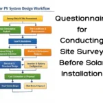
Questionnaire for Conducting Site Survey Before Solar Installation
A proper site survey is critical before solar installation. This questionnaire helps evaluate roof condition, load requirements, shading, and electrical infrastructure to ensure accurate system design and optimal performance.
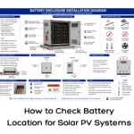
How to Check Battery Location for Solar PV Systems
A complete guide to solar PV battery location assessment, helping installers select safe and efficient locations for battery storage systems.
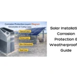
Solar Installation Corrosion Protection & Weatherproofing Guide
A complete guide to solar corrosion protection and weatherproofing, covering methods to prevent seepage and structural damage in solar installations.
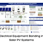
Electrical Equipment Bonding in Solar PV Systems
A complete guide to electrical equipment bonding in solar PV systems, including anti-oxidant application, compliance requirements, and safety best practices.
Demystifying Battery Backup: Everything You Need to Know
Battery backup is essential for uninterrupted power at home and in industries. This guide explains different types of battery backup systems, how they work, their benefits, and tips to choose the right one for reliable energy storage.
How to Connect a Solar Panel to an MPPT Charge Controller: Step-by-Step Guide
This guide explains how to connect a solar panel to an MPPT charge controller step by step. Learn correct wiring, safety tips, and best practices to ensure efficient and reliable solar power performance.
Installation of DC Energy Meters in Solar PV Systems: Step-by-Step Guide
DC energy meters are used in solar PV systems to measure generated DC power and energy. This guide explains installation, wiring, testing, and safety procedures for solar installers.
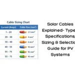
Solar Cable Guide | Types, Sizing & Specifications for PV Systems
Solar cables play a critical role in ensuring efficient and safe power transmission in PV systems. This guide explains cable types, specifications, sizing methods, and best practices for selecting the right solar cables.