In solar photovoltaic (PV) systems, electrical cables form the backbone of power transmission between solar modules, combiner boxes, inverters, batteries, and distribution panels. To ensure safe and reliable system operation, it is essential to verify that all electrical connections are properly installed and functioning correctly. One of the most important tests performed during solar installation and commissioning is cable continuity testing.
Cable continuity testing helps identify broken conductors, loose connections, incorrect wiring, and open circuits before the solar PV system is energized. Proper continuity testing improves system reliability, reduces maintenance issues, and ensures safe solar electricity generation.
Improper or skipped continuity testing can result in power losses, system faults, equipment damage, and increased solar installation charges. Therefore, solar installers and EPC professionals must understand proper continuity testing procedures, tools, and safety precautions.
Electrical testing and verification are essential parts of renewable solar projects and solar energy for home use.
This blog provides a complete guide to cable continuity testing in solar installations, including testing methods, tools, procedures, safety practices, and best practices.
What is Cable Continuity Testing?
Cable continuity testing is the process of checking whether an electrical conductor has an unbroken path for current flow.
The test confirms:
- Proper cable connection
- Absence of open circuits
- Correct wiring paths
Continuity testing is performed before system energization to ensure installation quality and safety.
Importance of Cable Continuity Testing in Solar PV Systems
Proper continuity testing helps:
- Detect damaged or broken cables
- Identify loose electrical connections
- Prevent short circuits and faults
- Improve system safety
- Simplify troubleshooting
- Optimize solar panel system cost
Skipping continuity testing can increase:
- Downtime
- Maintenance expenses
- Solar installation cost per kWh
Components Requiring Continuity Testing
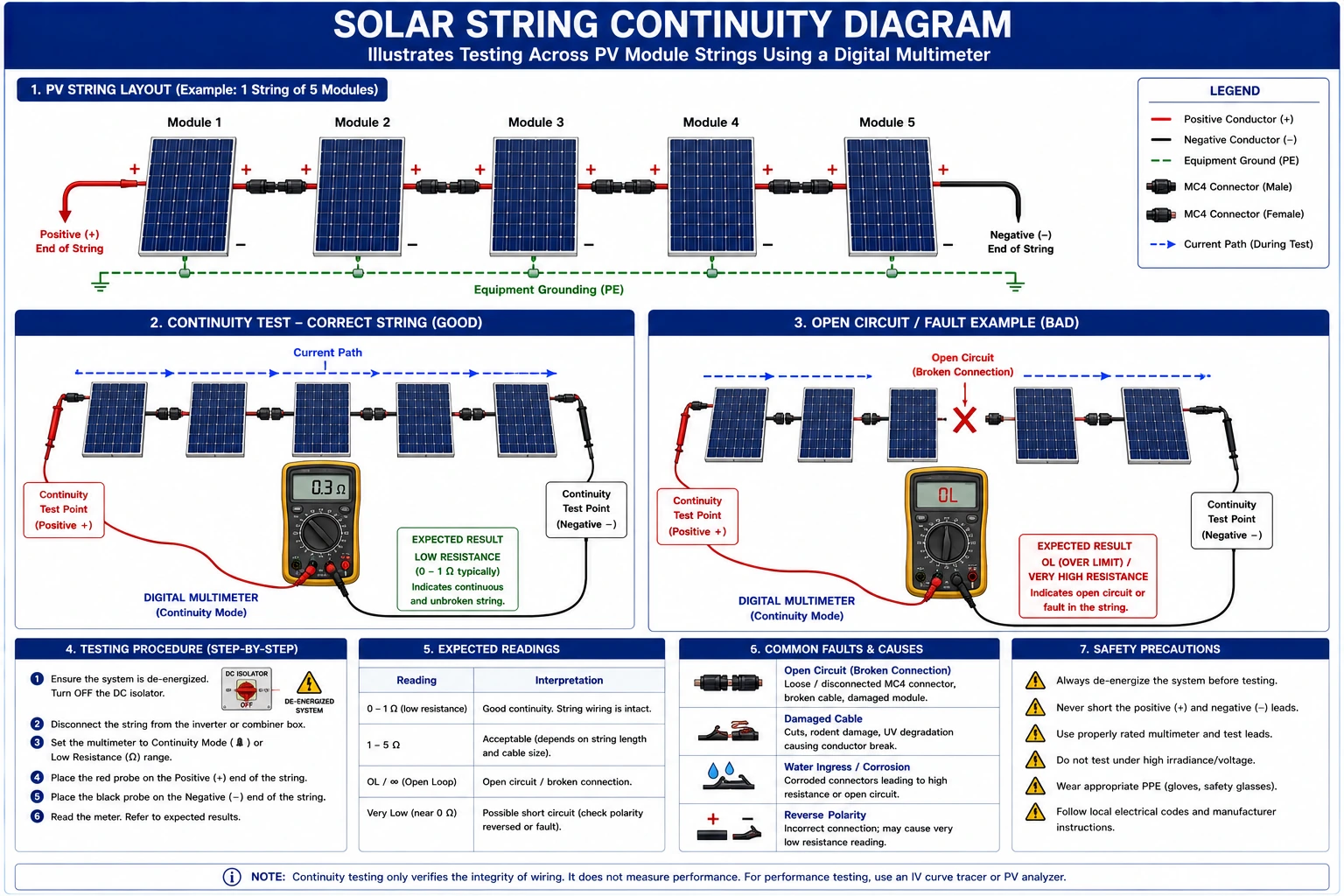
1. Solar Module Cables
- Checks DC string continuity.
2. DC Combiner Box Wiring
- Ensures proper interconnection.
3. Inverter Input and Output Cables
- Verifies DC and AC cable integrity.
4. Battery Interconnection Cables
- Confirms proper battery bank connections.
5. Earthing/Grounding Cables
- Ensures safe grounding continuity.
Tools Required for Cable Continuity Testing
1. Digital Multimeter
Most commonly used for continuity testing.
Features:
- Audible continuity buzzer
- Resistance measurement
2. Continuity Tester
- Dedicated tool for quick continuity checks.
3. Insulation Resistance Tester (Megger)
- Used for advanced electrical testing.
4. Test Leads and Probes
- Provide secure electrical contact during testing.
Pre-Testing Preparation
1. Review Electrical Drawings
Study:
- Single Line Diagram (SLD)
- Cable routing plans
- Wiring layouts
2. Isolate All Power Sources
Before testing:
- Shut down the inverter
- Disconnect solar modules if necessary
- Isolate the battery bank and the utility supply
3. Inspect Cables Visually
Check for:
- Physical damage
- Loose connections
- Burn marks
- Improper terminations
Step-by-Step Cable Continuity Testing Procedure
Step 1 – Set Multimeter to Continuity Mode
Most multimeters indicate continuity mode with:
- Sound wave symbol
- Diode symbol
Step 2 – Verify Multimeter Operation
- Touch test probes together to confirm buzzer operation.
Step 3 – Disconnect Cable Ends
- Isolate both cable ends from the equipment before testing.
Step 4 – Connect Test Probes to Cable Ends
Place:
- One probe at one cable end
- Second probe at the opposite end
Step 5 – Observe Test Results
If Continuity Exists:
- Multimeter beeps
- The resistance value is very low
If No Continuity Exists:
- No sound
- Infinite or high resistance reading
Step 6 – Record Test Results
Document:
- Cable identification
- Continuity status
- Resistance readings
Continuity Testing for Different Solar Components
1. Solar Module String Testing
- Ensures proper series and parallel connections.
2. Inverter Cable Testing
- Checks AC and DC cable integrity.
3. Earthing Continuity Testing
- Verifies proper grounding connection.
- Ground continuity is critical for personnel safety.
4. Battery Cable Testing
- Confirms proper battery bank interconnections.
Common Cable Faults Detected During Continuity Testing
1. Open Circuit
- Occurs due to broken conductors or loose terminations.
2. Incorrect Wiring
- Wrong cable connections between components.
3. Damaged Conductors
- Mechanical damage or improper installation.
4. Corroded Connections
- Causes increased resistance and poor performance.
Quality Checks After Continuity Testing
1. Resistance Value Verification
- Ensure readings are within acceptable limits.
2. Cable Label Verification
- Confirm proper identification.
3. Connector Inspection
- Verify proper terminations.
4. Grounding Continuity Verification
- Ensure earthing effectiveness.
5. Documentation Review
- Maintain proper testing records.
Conclusion
Cable continuity testing is a critical quality assurance process in solar PV installations. By verifying cable integrity, identifying wiring faults, and ensuring proper electrical connectivity, installers can significantly improve system safety, efficiency, and long-term reliability.
Electrical testing and verification are fundamental aspects of renewable solar systems and solar energy for home use. Additionally, adherence to standards established by the Ministry of New and Renewable Energy ensures safe and standardized testing practices.
With proper continuity testing procedures, solar professionals can optimize solar panel system cost, improve solar electricity generation performance, and support the successful deployment of renewable energy technology across residential, commercial, and industrial sectors.
FAQs
Q1. What is the purpose of cable continuity testing?
Ans: It verifies that electrical conductors have a complete and unbroken path.
Q2. Which tool is commonly used for continuity testing?
Ans: A digital multimeter is commonly used.
Q3. Why should continuity testing be performed before energizing the system?
Ans: To detect faults and prevent equipment damage.
Q4. Does continuity testing affect solar panel system cost?
Ans: Yes, proper testing reduces maintenance and repair expenses.
Q5. What safety precautions should installers follow during testing?
Ans: Use PPE, insulated tools, and test only de-energized circuits.
Solar Electrical Installation Toolkit: Inspection & Usage Guide
A complete guide to the electrical installation toolkit for solar installers, including inspection procedures, tool usage, and safety practices.
Sloped Roof Solar Anchors & Attachments Installation Guide
A step-by-step guide to sloped roof solar anchors installation, covering roof attachments, fixing techniques, and best practices for durable and leak-proof systems.

Fire Hazard in a Solar Setup at Rice Mill, Kaithal – Case Study and Safety Insights
A recent fire incident at a rice mill in Kaithal highlights the critical importance of safety in solar installations. This case study analyzes the root causes, system faults, and preventive actions that can help industries avoid similar hazards in their solar setups.
How to Connect a Solar Panel to an MPPT Charge Controller: Step-by-Step Guide
This guide explains how to connect a solar panel to an MPPT charge controller step by step. Learn correct wiring, safety tips, and best practices to ensure efficient and reliable solar power performance.

Minimum Land Requirement for Solar Power Plants in India
Understanding the land requirement for solar plant projects in India is essential for accurate planning and approvals. This article explains minimum land needed per kW and MW, key influencing factors, and differences between rooftop and ground-mounted solar plants.
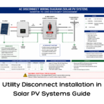
Utility Disconnect Installation in Solar PV Systems Guide
A step-by-step guide to utility disconnect installation in solar PV systems, including wiring, safety measures, and installation best practices.
500 kW Rooftop Solar for Industries in India: Complete Guide 2026
A complete guide to 500 kW solar for industries covering installation cost, energy generation, ROI, savings, and why it is a smart business investment.
Delhi Government Pledges to Boost Renewable Energy Generation
Delhi, the capital city of India, is moving towards a greener future with an ambitious plan to generate an additional 6,000 MW of electricity using renewable energy sources.